Search the Community
Showing results for tags 'Axle'.
Found 23 results
-

[WIP] Rate my axle setup
damian_kane_iv posted a topic in LEGO Technic, Mindstorms, Model Team and Scale Modeling
I'm trying to design a realistic 5-link axle for an upcoming crawler idea. I wanted to make a genuine 5-link with as much travel as possible and a differential locker. I think I have the geometry 99% there. I also plan to add pneumatic shocks to complement/dampen the coil springs. Lego's new springs were appealing and compact, but the 9.5L springs have much more travel needed for high axle articulation. Let me know what you think/how it can improve: Here you can see the coils, the shock and most of the suspension links. This is a close-up with the pneumatic cylinder removed. The axle is designed for ~1:9-1:11 sized mocs and can be fitted with either a portal axle mounts (pictured here), or traditional ungeared mounts. Here you can see the lower control arms, the panhard rod, and diff locker. Here's a picture of the underside. I based this design off of Madoca's Dacoma axle. This was originally designed to accommodate a power ball joint for a more trophy truck-like suspension, but I have converted it into a 5-link axle design and scaled it up for 1:10 models. Finally, the underside of the chassis contains the upper control arms, mounting for panhard (bottom), and the driveshaft As you can see, this was formerly a powerjoint setup and can be converted back if desired. -
 I'm prototyping a small scale Dune/Trophy Truck chassis that I want to make instructions for at some point. I got two interesting iterations so far: The first one is buggy-style with rear engine and rubber-band front suspension. the second one is more of a truck, has a front engine and all shock suspension. Additionally I had some interim iteration between those two that I didn't made a video of, but it had some interesting features as well: Gallery for this build: https://imgur.com/a/6umV5zm I'm still not fully satisfied with what I've got so I'll iterate some more on the front suspension and the chassis structure itself before I can make instructions, but I hope you'll find some of the techniques interesting. Also check out my channel, more cool stuff out there, I promise :)
 -

wheel lock for RIM 55982
janssnet posted a topic in LEGO Technic, Mindstorms, Model Team and Scale Modeling
Hi there, While building a small rc car using a RIM 55982 (18 x 14) I needed a way to lock the wheels to be able to drive it with a motor. Almost started drilling holes ..... and then, after removing the tire, it turned out there is a little notch inside the wheel. Looks like it is a space for a tiny piece of plastic to slide in, to lock the axle to the wheel. Exactly what I'm looking for! Have I missed something? Is there a LEGO part that fits this notch and locks the wheel? Or should I make it myself. https://drive.google.com/file/d/1UgLxSAbwba1zWIg1YRPNkqPdqAq3pMu7/view?usp=sharing -

[POC] Axle twister
Touc4nx posted a topic in LEGO Technic, Mindstorms, Model Team and Scale Modeling
Have you ever had some straight axles ? Who need those ? That's why I present you the Axle Twister. You just have to replace the pink axle, with the one you want to twist. then power the XL motors and "voilà" your axle is now twisted. Final ratio is 1:0,12 Feel free to use it to twist your axles :) Have a fishy day. -

[HELP] About Bracing Front of Axles
StudWorks posted a topic in LEGO Technic, Mindstorms, Model Team and Scale Modeling
In my car MOC, I braced both sides of most of the driven axles so when moving the axles won't wiggle out of the beams from the torque. In the example pictures below, I was wondering if the first picture, with the brown 3L with stop is good enough for use, or if I should always place a beam in front of it to prevent the 3L from pulling itself out (as shown in the second picture). Do I need to always prevent axles from pulling themselves out or is it fine without doing so? Any thoughts would be appreciated. -
I just finished a marathon session of adding approximately 160 bearings to my rolling stock. I am positively blown away by the results! It took hours and hours to do but cost only about $35 and the result is cars that seem to glide over the rails. I used the standard MR52ZZ bearings that others have used. They measure 2x5x2.5mm. These fit the older Lego 1.98mm axles with the pointed end, the newer 2.00mm axles with the blunt end and your custom .078 inch (1.98mm) music wire axles. I used all three types for this project. Variances in tolerance will sometimes require a hammer to tap the bearings on to the thinner axles, but the thicker ones require quite a pounding for each. I drilled a hole in a board to the correct depth to help seat the bearings when hammering. I used the yellow brick to verify the correct depth on each end and the jig ensures everything is centered. The hammering DOES damage the bearings! Don't be fooled. BUT, it doesn't matter. My cheap Chinese bearings went from icy smooth to "spins very well" after hammering. My cars now roll for yards with just a flick. A few (2-3?) bearings were destroyed; they became notchy and wouldn't spin freely after hammering. So off they came and into the trash they went. At less than $.20 each I could afford to toss a few. I never plan to reverse this mod, nor sell these parts so I don't care about cutting those two tiny tabs off. That said, this mod could be done and could be reversed without removing those tabs. If anyone's interested how let me know. I also used a tiny drop of thin CA to hold the bearings to the truck. That prevents them from popping out and from shifting left or right and rubbing against the inside of the truck. Did I mention I'm thrilled? I can now pull all my cars, at once, around the tightest curves and switches with a single train motor. Three of my engines have twin train motors specifically because they needed the traction provided by four driving wheels. I'm guessing that my battery life will improve also. Now I can start designing longer trains and adding more cars! Hope you like.
-
Problem: Gear Gets Pulled Out
StudWorks posted a topic in LEGO Technic, Mindstorms, Model Team and Scale Modeling
Recently while testing for gear skipping in my EV3-powered torque heavy MOC sports car, I found this... The 5L (I believe) axle holding the half-gear I'm pointing at, which is clearly visible from the issue, moves out of the half-gear every time it skips. Indeed the axles with axle connectors connected to this gear have a "sliding axle" issue. I made a light fix by adding another axle connector, but I don't know if it will stop the sliding. Here above is the axle being pushed in... and pushed out to its maximum. Above is the issue: This piece my right finger is pointing at is in where my left points at, and it seems to wiggle enough to be the main cause of the sliding. However, I can't fix it because there is no place to reinforce the small piece. It seems from the pictures above with the axle sliding in and out that it will keep the half gear in place, but I don't know if it would under torque. Here's what happened to the last gear I had in here... completely chewed out by the axle. Have anybody else dealt with this? Some helpful feedback on this issue would be appreciated. Happy building. -
Need Help With Drivetrain Reinforcement
StudWorks posted a topic in LEGO Technic, Mindstorms, Model Team and Scale Modeling
I was working on my MOC and I found there was a lot of gear skipping. The skipping comes from this, a small gear with bracing on only one side. The finger on the left points to what pieces the right points at. If I remove the bush that the right is pointing at, there is no other piece to put there, because it will rub against a 24t gear. I also can't make the axle longer because right in front of the bush is a 4L with stop with a different gear ratio. I can't find a solution in how to support this axle and I would appreciate some help, thank you. -
My "Axle Hole" Pieces Are Cracking
StudWorks posted a topic in LEGO Technic, Mindstorms, Model Team and Scale Modeling
Just building my MOC and I found out pieces I thought were in great condition are forming cracks already. 1. I thought only grey pieces were prone to these types of cracks, I was wrong. 2. Lots and lots of broken grey pieces. Almost every piece I have like this now has a crack. 3. Here's the same pieces but showing the cracks on the other side. 4. U-joints are just so easy to break. 5. I even broke one of these. 6. To test the durability of this piece (which some I have are in the earliest phase of cracking) I put an axle halfway through, put pressure on it, and the piece's "axle inserter" snapped. Trying to stay positive, but this is really holding back my builds. Wish I could find some way to prevent this from easily happening or if the cracking is a defect with the part. Is anybody else experiencing cracking with pieces where you put in axle? Would like some feedback from the community, thank you. -

Rotating Axle with Varial Offset
ancientpixel posted a topic in LEGO Technic, Mindstorms, Model Team and Scale Modeling
Hi All! Often a "reader", now a "poster", i´ve got a problem i cant fully wrap my head around. I try to keep a steering axle straight while going through a pivoting point or turntable. The axle should rotate with the pivot (eg in the picture below the yellow bricks should always align with the grey liftarms even if the liftarms are at 90 degrees of each other) but i want to rotate it manually on one side, with the rotation + offset of the pivot on the other side. Like the axle itself would have been twisted. The furthest ive got with this is pictured below and works as long there is no friction on the left output. I want both sides to rotate at the same time, but if you rotate the pivot/turntable then it should add just an offset "within" the axle. I dont know if this is actually possible or how to split the axle in two, add the pivot rotation to one part and then add both rotation together. -
So most everyone i've seen likes to add drive to their front axles. I'm having trouble building a dead front axle for my truck. I'm no good at steering geometry either. Here's what i've come up with so far. Right now it works for what it is, but could use improvement. If anyone has any ideas or links, please share. I'll try to add some pics.
-

Rapid Shooter Trigger (18587) in Wheel Hub (11950/11949)?
GoldCivetta posted a topic in LEGO Technic, Mindstorms, Model Team and Scale Modeling
I was wondering if these parts: Could connect with this part: I want to know if we can use these wheel hubs for smaller wheels that don't have those 3-pin connections, such as these: -
.thumb.png.116032e930e483fb4ebbfdc62183bd34.png)
[TIP] Use rubber connector to avoid rim from sliding of axle
Didumos69 posted a topic in LEGO Technic, Mindstorms, Model Team and Scale Modeling
Hi, For the AWD platform that I'm working on (project 'Steppenwolf') I've been looking for a way to better fix the rims to the axles (5.5l with end stop) coming out of my self-composed wheel hubs. I ended up shoving a rubber connector (damper) onto the axle and squeeze it between two 2l lift arms. The short lift arms are attached to three 3l pins that are inserted into the rim and held in place with three more 1.5l pins and a belt wheel covering the hole thing. See image. The image has been rendered, but I applied this in real life and it actyally works, even in a setup with high suspension demands such as my AWD platform. The idea may of course also be applied to the similar rims with 6 pin holes. I thought this might be useful for others and may even look good on truck-like vehicles. The whole thing may of course also be placed on the inside of the wheel, but in a steering setup that would move the center line of the wheel away from the virtual kingpin, which I personally don't like. Regards, Diederik -

[HELP] Reducing Wobble in Axle
A Gallifreyan Cat posted a topic in LEGO Technic, Mindstorms, Model Team and Scale Modeling
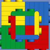
So I made a small scale solid axle just for fun and I think it turned out quite well, but it wiggles side to side a bit too much. Here are some pictures. Any thoughts would be greatly appreciated. Those are the pictures of the axle, now here is the problem. The above two pictures show the extent of the wobble. -
Location: F02 - Lesser Drigo Tags: Spaceship, Land Vehicle Back aboard the Axle, Pilot John Hannibal prepares for a new mission. As the trolley pulls in to take the pilots to their ships, he has an extra bounce in his step. The company's needs are starting to coincide with Hannibal's own ambitions and he is happy to be leaving for his last mission based out of the Axle. [O - F02] HANGAR 2 by Ryan McBryde, on Flickr The Axle has become a great ship under Dr. Long. Ever moving, steadily humming, never boring. It was larger than most capital cities and was the heart of Octan's presence in this galaxy. Every deck was it's own community of mechanics, scientists, cooks, farmers, engineers, entrepreneurs, civil servants, firefighters, artists, teachers, mothers, fathers, drivers, pilots, barbers, tailors, dancers, bartenders, medics, tattoo artists, and the occasional special forces agent. Everything moved in complete chaos and unison. Every body had a purpose and every action a mission. But Octan would need more Axles if it was going to maintain its position in the galaxy. [O - F02] HANGAR 3 by Ryan McBryde, on Flickr Hannibal is dropped off at his newest delivery, a heavily armored jump ship needed by the driver crews working on F02. [O - F02] HANGAR 4 by Ryan McBryde, on Flickr His next mission would depart from F02, so this was goodbye to the Axle, for now. [O - F02] HANGAR 5 by Ryan McBryde, on Flickr C&C very much appreciated. Thanks.
-

Is there an alternative for this driveshaft solution?
Omikron posted a topic in LEGO Technic, Mindstorms, Model Team and Scale Modeling
This thing is awesome on large scale models but I'm looking for more compact solution if there is any, since I don't want to upscale my model just to fit the scale of this part. Any suggestions? -
Hi I am working on gear pairs meshed directly together, in a 2 by 2 arrangement. Two gears on each of the two axles - However one gear is an idler gear which is driven by the other gears instead of with the same rotation speed as the motor. However I'm not sure if the ratio for the idler gear will be 1:1 since there is two 16 tooth gear gears in either example I don't think it is 1:1 though it should be what the other two gears are, so say 3:1 or 1.6:1 but I'm unsure as it's hard to tell. The yellow axle joiner goes to the motor, I'm using a differential to replicate a single 24 tooth idler in the first image. Obviously the dark grey gears are the idlers. Any ideas what it could be. More gears can be used with studed beams and plates such as 16 tooth +12 tooth or 20 + 20 or 16 + 20 etc. Regards, S
-

New part: Technic Axle 5L with stop
legolijntje posted a topic in LEGO Technic, Mindstorms, Model Team and Scale Modeling
Hi, I just downloaded the measurements page from the Technic website, and it shows a dark tan axle 5L with a stop. Is this a new (unknown) axle? Or is it a wrong file and it should be a 4L tan axle with a round middle. Or was I just laying under a rock last months? -
Hi, I have two idler/clutch gears on an axle with a clutch between them, how do I have both gears spinning when the gear lever is in 'neutral/middle' but when the clutch is put into gear 1 or gear 2 only that one spins.? Obviously more axles and gears will be underneath the above setup since its a gearbox. Note that I cant put any more gears on the same axle as the clutch as: 1 it slides with the clutch, through the idler gears 2: the axle isn't long enough Maybe a differential can sort this I'm not sure, its really hard to picture it out mentally but I'm sure its possible, I know that a differential can have just the pinion gears or everything rotating. I don't want to use any more clutches as the gear lever already is using 4/5 of them and its very wide as it is. Here is the split/assembled model, grey and black parts are technic nuts and threaded axle.
-

New Prototype Crawler Axle
z3_2drive posted a topic in LEGO Technic, Mindstorms, Model Team and Scale Modeling
April Fool's day has passed, so it's time to get serious. After building my large speed chassis with the new hubs, I was so eager to build I disassembled it right away I think I have a video, but not completely sure, because I deleted some... Anyway after a couple days of messing around with various ideas I came up with a solid prototype. Features are: 4 link connections, gear reduction 1:9-using a nifty reduction right before the 5x7 frame(which has knob wheels so I don't break any bevel gears), a telescopic driveshaft which I got from a youtube video-not sure who it was by; new 8t gears, and to top it off, my 1.9 Rok Lox tires Photos: I guess I will build a chassis then the front axle. This crawler will probably use buggy motors considering the reduction. -
Lego tatra T813 4x4 RC Trial Truck V4
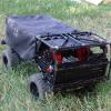
The Ghost Racer posted a topic in LEGO Technic, Mindstorms, Model Team and Scale Modeling
Lego Tatra T813 4x4 RC Trial Truck V4 The famous Tatra T813 in Lego remote controlled version, versatile and durable as the original. Modular Design The scale model, made by me after several months of work, contains most of the features found in the real version, to significantly affect its performance are the axle shafts, transmission, suspensions, chassis structure and weight distribution. Specifics -weight: 2Kg -height: 225,0mm, 22,50cm -lenght: 400,0mm, 40,00cm -width: 215,0mm, 21,50cm -3 XL Motors (2 for drive, 1 for sterring), 2 IR Receviers, 2 Battery Boxes Motor For Lego Tatra T813 I opted for the use of two XL Motors, which provide a high torque with an average consumption of energy, but low number of revolutions per minute. There are two transmission shafts (the real Tatra T813 uses one), each connected to a single engine, split the load energy, strengthen the chassis, but also to divide the stress that every engine needs to support. In the gear shaft there are numerous gear reductions with anti-snapping patented by me (final gear ratio 9:1). Suspensions Independent half-axles suspensions for each wheel, all-wheel drive and anti-snapping system between gears for maximum traction, unlike the original model, Lego Tatra T813 does not use differential: between Lego bricks there is no type of limited-slip differential, then, by inserting a differential whatever, at the first hurdle would stop the vehicle, and this should not happen. Axle shafts New axle shafts very strong, with anti-snapping system patented by me, gear reductions, increased torque transmitted to the wheels (final gear ratio 9:1), and steering (in the front). Wheels Individual tactical tires on each axle (94.3 x 38R). Comparison with the real model The Lego model made by me is very similar to the real one, in particular, the design of the cabin faithfully reproduced it based on original designs. Youtube's Video The video is of the V1 version, I will soon be making a new video. My blog's page For more information and news about this incredible model, please visit my web page dedicated to it,, http://gtathecomplet...trial-truck-v4/ -

Short Axle Connection
Boxerlego posted a topic in LEGO Technic, Mindstorms, Model Team and Scale Modeling
I've seen some topics suggesting the idea of cutting the axle to length when a axle is to small for the given axle connection by the axle connectors. Here is a simple example that show a 1-2mm gap that is between the axle and connector. What should you do in a situation like this? -

Did someone try 2 L motor on an axle instead of a differential?
midengineaddict posted a topic in LEGO Technic, Mindstorms, Model Team and Scale Modeling
In my next 8x8 crawler project I have the intention of trying a setup with the two rear axle with 2 L motor each (a motor for each wheel). the two front axles only will steer with a servo, an L motor and a differential on each axle... and all axles will be floating with 4 links and horizontal chock absorber. Did someone know if its a goon idea or if a topic already talk about this setup?