Search the Community
Showing results for tags 'signal'.
Found 15 results
-

1930's modular railroad interlocking tower MOC - real world MOC (finished 2/13/23)
Murdoch17 posted a topic in LEGO Train Tech
I was inspired to build this industrial-looking old fashioned interlocking Tower by set number 60009 (Helicopter Arrest) and a number of old towers in my hometown of St. Louis, Missouri. In addition, the unusually-placed signal arm attached to the building is inspired by an mid-1960s WWII-set black and white film, (The Train) in which a French signal tower very similar to this one is used for some sabotage of a German train and is subsequently blown up in an Allied air raid... and yes, they really did blow it up - no miniatures were involved! Here you can see the chimney flue on the rear of the building. There is an abandoned OCTAN tank car also visible nearby. Upstairs is a heating stove for those cold winter nights, six lever frames for moving switches and a signal board for showing which route is currently aligned. The bottom floor features a (empty) gas tank, a chest for emergency flares and torpedo's, a trash can, plus a telephone. "This is getting out of hand... now there are two of them!" The one on the right is my original switch tower, while the one on the left is my Dad's (slightly different) copy. He paid for the model and I built it. I ordered the parts last Sunday (Feb. 12th), the three orders arrived Wednesday and Thursday and construction on the copy was completed last night. (the 16th) Thoughts anybody? EDIT: 2/13/23: Real world photos added! -
Hi everyone, I'm Alex. I'm starting to build up a train layout and wanted to add a signal bridge. I've seen this design (https://www.pinterest.com/pin/503910645807246353/) on Pinterest and really liked but have not been able to find the last two pages of the instructions. Does anyone have the same design built or the finished instructions?
-
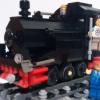
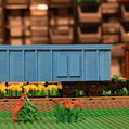
John looked at the signals ahead and said, "Bob, I know I'm the rookie conductor and you guys like to joke with me, but seriously, what do those signals mean?" Bob really took a hard look and then put the throttle of the GP39-2 into regenerative braking and slowed the train. "Those," he replied, "Means a roadmaster is out there trying to trick both of us." As the train halted short of the first red light, they heard a low moaning whistle from beside them. Moments later, a British steam locomotive roared by. "And that means we're not in Kansas anymore," he added, looking around for Rod Serling. I have been recently working on some trackside structures for my layout. I've built a mix of signals and a box for local control. From left to right, the overhead cantilever bridge is a Pennsylvania Railroad style with PRR position light signal on the left indicating stop and a modern hooded color light signal on the right indicating proceed. Under the signal bridge is a US style level railroad crossing signal (note the arm pivots to block the road), the back side of a Southern Pacific lower quadrant semaphore, a Southern Pacific lower quadrant semaphore with distant signal arm in the proceed position, a Deutsche Bahn semaphore signal in the Hp 0 (stop) position, a Deutsche Bahn semaphore signal in the Hp 1 (proceed) position, a US style signal indicating stop, a US searchlight style indicating clear, and a US color light "Darth Vader" signal indicating proceed. The GP39-2 is obviously based off of set 60052 (acquired a mostly complete extra). I build a custom frame and then modified it to look more correct as a CSX local freight locomotive. It retains the PF internals and motor. This signal tower is based on a few I saw while traveling around England and Scotland. The ground floor is empty, but could be easily filled with tools and other MoW equipment. The first floor has 'armstrong' levers to actuate signals and switches. Included is a coffee pot and radiator.
-
So last week I needed to open up a 12v 80's era signal unit as the green LED was starting to fail and I wanted to see if I could repair the unit, as second hand ones are close to £20 delivered to me. First job, break out the scalpel and unseal the unit... This gives us the components - front , back and circuit board... The red LED was working fine... The green one not so... It's a simple circuit design with 2 LED's and one resistor to drop the voltage to 2.2v Sourced some replacement LED's from eBay which will work around the 2.2v area... And then proceeded to unsolder the old green LED and replace with the new one.. Then time for a test.... All was good so the unit was resealed and ready for further duty. I've never seen the insides of one of these units or even any pictures on the web, so here you go.. Jonathan
-
Now that my semester is mostly over, I've been thinking about some of the projects I had to put on hold to focus on my senior design project this year - specifically, the PCB I developed a couple years ago to run two three-color track signals off a centralized microcontroller: The original design called for a three-color signal: red, yellow, and green. My plan was to divide my layout into blocks, with a signal placed on each block. I wanted my signals to respond in the following manner: - If a train is detected in a block, that block's signal must be red (block is occupied). - The signals in the blocks adjacent to occupied blocks must be yellow (block ahead is occupied). - Otherwise, the block signal will be green (block is unoccupied). This would result in the signals 'following' the train around the layout, such that any trains travelling on the same track would be aware of each other, hopefully avoiding collisions. In practice, I won't be running trains on the same track, but it's still a fun effect to have! My resulting truth table then looks like the following. Inputs A and S are the signals from the adjacent blocks and block sensor, respectively, while outputs R, Y, and G are the red, yellow, and green signals, respectively. It doesn't matter which 'side' I get a signal from an adjacent block, as either way I want the signal to turn yellow. In addition, if the block sensor sees a train, I don't care what the adjacent blocks are doing - the signal must turn red. After working through this table, it occurred to me that there were two ways I could build this signal controller... Form 1: NAND Logic This truth table is simple enough that I should be able to build it with basic logic gate ICs - and if I can do that, then I can do it purely with NAND logic gates, saving cost as I only need one type of chip to make this work. However, I still need to work on converting the truth table to a set of Boolean expressions, and from there into pure NAND logic. After doing a bit of research, it looks like I'll need multiple NAND chips, as most chips I find have only four gates inside them. However, I am space and cost limited, as I can only use four NAND chips (16 NAND gates) if I want to be comparable to the cost of the ATTiny85 at 36 cents per chip. Form 2: ATTiny85 Since I only have five inputs/outputs, the ATTiny85 microcontroller is perfect for this application - there are exactly five pins left over after accounting for power, ground, and reset. However, I would need to program each microcontroller, and doing so with a surface-mount device becomes problematic. The cost is also an issue, as each one costs about $1.16-1.25. Buying in relatively small quantities, I think I can get the cost of components for each board to about $5 per board - including connectors and such. The main issue with using NAND gate chips is the amount I'll need, and thus the space they'll take up on a size-limited board. I also will need some transistors to drive the LEDs as the logic chips can't drive that much current directly. The issue with using an ATTiny85 chip for each board is how to program the much smaller surface-mount versions, as well as the relatively large fixed cost of each chip - I can't work on optimizing out some of the cost in the same way I could with the NAND version. I want to use JST connectors for running cables between the boards and sensors and such, as they're directional and I don't have to worry about plugging things in backwards this way. There is another question I have for you all: what's the most useful form factor? My original project had a board that was designed to fit in a 4x4 stud area, but for this I'm leaning more towards a 2x6 or 2x8 board, as I think I can fit that into more spaces.
-

Gauging Interest: Control Board for Two Three-Aspect Signals
Phoxtane posted a topic in LEGO Train Tech
As part of my quest to control my Lego train layout with an FPGA controller, I decided that I would want some railway signals that would change as the train passed by. I then realized how much of a mess that would be with wires running to and from each LED in the signal and the control board, so I thought to myself: "I wonder if there's something I can build that will help with this problem?" I'm curious to see if there's enough interest in this gadget for me to be able to make and sell them, so that's the main point of this post. Here's the result: EDIT 8-2-2016: Board version 2.1 images In addition, here's a video of one of the first versions of the circuit, before I had even started on designing a PCB. This demonstrates the basic functionality of the controller with a single three-aspect 'signal'. Description: This board can drive up to two three-aspect (light) LED train signals with as few as two I/O pins on the chosen microcontroller. It can be run off of either 3.3V or 5V supplies* a 5V, and will interface with logic signals of the same voltage. If you'd like to drive the two signals independently, it will take four I/O pins. Dimensions: 4 studs by 4 studs, not including the male header pins. As I have yet to receive the prototype for this board, I don't know if the mounting holes fit a typical Lego stud, or if they line up with the corner studs on a 4x4 space - however, I should be able to adjust this without too many problems. The header pins are the standard 2.54 mm/.1 inch pitch popularized by Arduino microcontrollers. Technical Specifications: Supply voltage should either be 3.3V or 5V* be 5V. Absolute maximum current draw should be ~85-90mA, typically ~41mA**. Operation: The IC used to make this board work is the SN74HC139DR, a two-line to four-line decoder. There are two decoder units in each chip, and as a result this board will happily drive two signals at a time, either independently or synchronized together. The A0 and B0 connectors are the least significant bit of the two-bit signal, with A1 and B1 being the most significant bit. There is also an active-low 'Enable' pin for each decoder, which is not broken out to a header; it is permanently tied to ground so that the board is always ready to change the signal. If the value sent to Signal A is 00 (A1=0 and A0=0), all of the LEDs in the signal remain off. If the value sent to Signal A is 01 (A1=0 and A0=1), the green LED will turn on and remain on as long as the 01 signal is applied. If the value sent to Signal A is 10 (A1=1 and A0=0), the yellow LED will turn on (and remain on as above). If the value sent to Signal A is 11 (A1=1 and A0=1), the red LED will turn on (and remain on as above). Signal B works in the same manner. If you want to set both signals to the same light, simply tie A0 and B0 together, as well as A1 and B1 together. If you want to drive the signals independently, don't do that Cost: My calculations for the cost of the components, the PCB, and the time it takes for me to assemble and test each board tells me I should be selling these for $21.99 (USD) apiece. If I was to have these mass-produced, it'd likely be cheaper - however, I'd have to be buying them in quantities of 100, or 1000, and there's no guarantee I could sell them all. As such, I would prefer to take orders from anyone who's interested in buying these and essentially produce them on-demand so I don't have to keep inventory around. Sales Pitch: You should buy this device because it reduces the amount of I/O pins required to drive two three-aspect signals by 33% (four pins instead of six for independent operation) or even 66% (two pins instead of six for synchronized operation). This reduces the amount of programming work that has to be done by the user. In addition, the board is thin enough that it can fit in a single brick's height; as such, it can easily be hidden under some landscaping or even placed under the ballast for a section of track! Moreover, it comes in a lovely purple color with a gold plated finish, thanks to the company who I get my PCBs from. <~~~~~~~~~> *The only change that this would require would be different values for the resistors; I currently have resistors on hand for a 3.3V version, as that is what my FPGA operates at. Typically, Arduinos operate at 5V, so I could potentially offer either variant to suit your needs 5V supply only! More will burn out LEDs and resistors, less will cause undervoltage problems. **The LEDs I prototyped with (and will use on my layout) have a maximum current draw of 20mA apiece, with the IC drawing ~1uA. If there's a problem with floating inputs, it is possible for two LEDs on each signal to be lit at a time, resulting in double the current draw. I have yet to see all three LEDs on at the same time! Now, having read all of this above: Would you buy this gadget? If so, how many do you think would buy, and how much would you be willing to pay for each one? As sad as it is to admit, I'm not able to compete on cost with cheap PCB assemblers in China. Another question: Would you want mounting holes on the board, similar to what I've show here? If so, would you want them to fit a Lego stud? Finally, just to make this clear: I'm not ready to sell these yet. I still have to receive and assemble my prototype, which isn't even the board pictured above (it is functionally identical, just without the helpful pin labels and slightly cheaper because it's a tad smaller). I'd be thrilled to be able to sell these to people once I've verified that it works and doesn't explode, however! -
Hi all! This is a small idea that I had quite recently as an item that could be found in a set that added playability to a Lego train set. It's less for show displays and more for a child's little Lego City oval of track in their room. There's no electricity, just a mechanism that'll hopefully make it feel like the operator is a signalman! It's not based on any particular signal box, but the signal is very clearly an old British design. The box is cut in half to reveal the interior of the box and to provide access to the lever of the mechanism: It's a very simple set-up, with the mechanism being the most complicated aspect to it. Here's a (VERY) quick diagram of the mechanism: I'd love to hear any comments or suggestions to improve this! I might put it forward to Lego Ideas in the near future, maybe with a little train to go with it! Many thanks, Isaac
-
Hi, I have a very special problem: For an exhibition (the day after tomorrow) I will use 12V-lights at my train station. I tried this function with a gray 12V transformator and the switch with the train crossing pattern: (set 5083). Everythings worked and I was happy. Right button turn the lights on, left button turn the lights off. Everything is fine. But: Now I need this remote Control switch to use the train crossing, but I had another set 5081 - remote control witch SIGNAL pattern. I opened (because it was sealed (ovp)) and I tried to use ist. But it doesn't works. I think, it isn't broken. I think the reason is to find into the different between these both switch. The signal one stayed "down", after I pressed the button, and when I press the other button (red or green), the first button comes up. The switch witch train crossing pattern works so: If I pressed any button, the button comes up immediately. Also the train crossing has 2x three holes and the backside, the signal switch has 1x five holes and 1x three holes. Could someone help me to understand the function. And: Why I couldn't connect normal light bricks with the signal switch. Does set 5080 works (Remote control for switch). Or does the switch in set 7862 works? Please help me. Michael
-
Hi, Please check out pictures of my Lego Bat Mobile (original movie) with working Bat Signal on my web site www.Legoavatar.com.au or visit Lego ideas and check out my projects under Legoavatar. The Bat Signal actually throws out the Signal in a dark room!!! Also see my other projects, Lego Avatar Mech, Scorpion, Sampson and Lego Football with Stadium...
-
Good morning, Quick question . . . and I have looked through the forum for answers and come up empty handed thus far, there's lots of DIY stuff, but I'm working on a theory and I've found the parts that I think that I need on bricklink. I have a working theory and just want confirmation. If I have . . . . .the two rails with the missing triangle, a regular remote control like 7863 would I be able to control trains stop & go or no. I've never had a 7860 set, and I still mean to get one. But does the remote work the same way as others do?? Then you add the whole red light/green light thing and that only gives you the visual in terms of if the train can go or not? If I had one of these sets I'd just do all of this experimenting on my own. While I'm asking stupid questions. The 7864 set (the actual Transformer), if you assemble the whole technic top assembly and remove the dial, does that thing actually stay together well or does it disintegrate the second that you try to use it?? Third question. If you disassemble a PF cord at one end and plug it into a 12V track while it's already plugged into the 12V transformer and then bridge the positive and negative sides of the track, is it possible to create a time portal that will take me back to 1985?? Thanks in advance.
-
Here is my Victorian-inspired train station and signal tower. If I made a topic about the station before, I am sorry. I'm reposting it as I couldn't find it. First up is the station: Background info: This station was built between the East & West Barrett's Tunnels in 1893 by the Missouri Pacific Railroad. It was used until 1944, when the war-time traffic became too much, and the two single track tunnels were bypassed by a double track cut-through built right next door. The Station and the West tunnel were preserved, while the East tunnel was covered up and buried under a road, which was eventually named Barrett's Station Road. The site of the station was turned into a museum known as the Museum of Transportation. Builder's notes: This station was originally the Toy Shop from the Winter Village series of LEGO sets. In real life, the story I just told you is 100% true. However, the Barret's station was not made in 1893, and looks nothing like the one seen here. The inspiration for the station came from the real-life Kirkwood Railroad Station which was built in 1893, is still used by Amtrak and is located a short distance up the track from the Museum of Transportation. Their are supposed to be printed 1x1 tiles spelling out BARRETTS on the sign on the front on the station. The other version I uploaded yesterday of this station will not work with my budget, so I went back to the drawing board and looked at my original station made from set 10199. I then combined the best of both stations into this model. This station is the fourth station I have made from 10199, and uses mostly parts from the second version from 2013. Here we see the station separated into it's modular components: - left platform - right platform - station building with access ramp (lower level) - station building and roof (upper floor) - station building tower roof The inside of the station features the following on the first floor: inside seating, stone fireplace, and a old-fashioned cash register for ticket sales. (This piece: http://www.bricklink....asp?P=3039pb26 ) The second floor (tower) is a employees-only area and houses some machinery. Here is the brand new street side of the station. This side includes an overhang that protects passengers from the rain.\ Next is the tower: Fictional History: This tower was built in 1893 at the same time as Barrett's Station, to control the single track mainline. The tower was updated in 1928 with modern controls and bypassed in 1944 by a double-track cutoff to avoid the bottleneck of the two single-track Barrett's Tunnels. The tower was preserved by the Museum of Transportation and has been recently turned into a public lookout point for the busy Brick Railway Systems mainline. Builder's Notes: This is a Signal tower that matches the color scheme and design features of my Barrett's Station model. This Victorian-era tower features a signal bridge, a spiral staircase to connect the two floors and a signal / switch computer from more modern times. The story on Barrett's Station is inspired by real life, but the real station was a one story affair and had no tower accompanying it. The Museum of Transportation does exist, however, and there is an elevated platform (at the way back of the property) to watch Union Pacific trains go by every fifteen minutes or so. The first floor features the spiral staircase. The signal arm disconnects from the first floor, and is attached to the second floor. The signal arm is a modified version of the one at the L Gauge website. (Link: http://lgauge.com/ ) The second floor features the control panel for the lights, and a desk for dispatching orders to the train crews, or in this case, holding a newspaper. The (updated) LDD file for the station is here: http://www.mocpages....1428338100m.lxf The LDD file for the tower is here: http://www.mocpages....1419790555m.lxf This model was inspired by set 10199, Winter Village toy Shop. The model is up for a remodel into a double sided version with a bigger interior, so I though I'd take some pictures while it's still together in this form. The platform splits off into three parts: left side (which is about three tracks in length) right side, (which is about one track long) and the building itself. (which is two tracks in length) The building is open backed, and features a desk on the top floor and ticket counter with cash register on the first floor. Comments welcome!
-
I don't know if anyone else has done this, I did do a (quick) search on this forum and couldn't find any posts, but I've hooked up 2 12v signals to my 9v tracks to get fully operational remotely controlled, albeit old fashioned wire style, signals controlling the 9v track in the station. Here's the pic, with an explanation below. DSC00221 by andyglascott, on Flickr I used the 9v wire/contact piece on the same side of the track with a small piece of paper wedged in the join between two 9v track pieces to break the circuit. The two contact pieces are visible, one in the white wall and one under the platform just in front of my Irish Rail loco. There is a second piece of paper similarly wedged further down the track to create the block of isolated track. To switch between 9v and 12v connections I used 1 of these electric wires, took one of the 2 x 2 connectors off and replaced it with 12v plugs. That connects to a 12v signal switch, connected to a regular 12v transformer. There's video on of it all working, complete with the familiar clicks of the 12v switch in the background.
-
Hey Guys I found This MOC Someone Made under name of "camlegofun" who made a great simple Lighted signal! I was unable to get the picture but you can see his/her work at LEGOIdeas: https://ideas.lego.com/projects/71391 Maybe we can make this become a reality? Just thought it would be good to share it, Rail Co Update: He has updated the page explaining it better and even a V2 design.
-
Ever thought that the price for the 'stop' rails was a little too high? I did, so I thought to modify a stock straight rail. As you can see from the picture below, I have made a good approximation in my first attempt. I used a Mk I rail, but you can see in the picture on the left there is a Mk II rail. Belatedly I found that these come with two plug contact points, so making them easier to convert:-)! Differences to note: The square plastic piece that sits in between the break in the rail. And the extra plastic directly underneath the plug socket to accommodate the hole. The rail was cut using a dremel, and the plug contact was formed by making small cuts and then folding with pliers. The hole was drilled with my dremel mounted horizontally on a piece of board in lathe like fashion. A piece of plastic was temporarily MEK'd to the top to minimize burring. The plastic pieces were measured and cut from a doner piece of track, and then welded in place with MEK mixed with a small amount of plastic shaving from the cutting. The end result is not bad. Next time I will seek out the Mk II's with plug holes, as these already have the two plug contacts formed! You could use this technique to replace your original stop rails that have gone rusty. Take care not to mix Mk I and Mk II rails as they are slightly different, the male connecting pin on a Mk II has plastic reinforcement. see pictures above. And make sure you use the plug holed variety, ogeL did make rails without connection points!
-

Replacing 12v Signal circuit, or leading up to another MOD.
Andromeda posted a topic in LEGO Train Tech
Hello All, I've been busy again. I've managed to copy the inside circuit from a 12v signal 2 x 3 brick, onto strip board. I've got some thin 1.5mm black ABS plastic sheet lying around, so I'm probably going to butcher a black 2 x 3 brick at some point. In the mean time here are a few pics of the circuit: And working side by side: Thanks for watching!


-Mini.thumb.jpg.03594ed3626ab4a4b625a32af4d03d5f.jpg)