Search the Community
Showing results for tags 'render'.
Found 86 results
-
How to apply custom decals on LDD renders
BEAVeR posted a topic in Digital LEGO: Tools, Techniques, and Projects
You may have encountered it: you built a nice model in LDD, but it looks surreal because it lacks decorations on e.g. the minifigs. This tutorial is here to help you with that. In this little tutorial, I will try to explain how you can enhance the POV-Ray renders of your LDD models with custom decorations. You can design entirely new figures for example, or you can apply the decorations that aren’t available in LDD. My example in this tutorial will be a stormtrooper minifig. This figure lacks all decoration in LDD, and is commonly used in digital Star Wars builds. It gives me the opportunity to explain how to decorate surfaces that aren’t directly accessible in LDD, how to fit custom decals and explain the general principles. This method doesn’t involve any hacking and doesn’t require any sick programming skills (although the custom decorations might need your artistic talents…). And the best of all: all programs I use here are entirely free! I’ll be using Lego Digital Designer, LDD2POV-Ray, POV-Ray and Inkscape. So let’s get started! Decorate the target pieces in LDD LDD2POV-Ray, the program that will eventually place your custom decorations, can only replace already applied decorations. So firstly, you need to give the pieces you want to decorate a replacement decoration in LDD. Make sure to use different decorations for each surface, so that you later can keep track of which filler to replace with which substitute. Also, taking a screenshot for reference is not a bad idea to support your memory. But wait a minute… Some parts don’t allow for any decorations at all in LDD! Minifig torso’s are not a problem at all, but things like helmets are a whole different story. But luckily, there is an easy way to apply decorations that will work in most cases (no guarantees though!). You have to export your .lxf file to the LXFML format (File -> Export Model). This .lxfml file is actually a textual representation of your model. Among others, it contains a list with the placed parts, including their color(s) and decoration(s). To find your part, use the search function (Ctrl + F / Cmd + F) and type in: in which you replace 30408 (the designID of the storm trooper helmet in this example) with the designID of the part you desperately want to decorate. You can find this ID by clicking on the part in LDD and looking at the bottom left corner. If multiple of these parts are available, you can give the specific part a different color and check for the one that says materials=”26” in which you replace 26 with the number of the color you used (you can find this number by hovering over the color in the color menu in LDD). The key part is then to change the part that says decorations=”0,0,0” in which the amount of zeros dictates the amount of surfaces that you can decorate. If the line isn’t present at all, you’re out of luck and won’t be able to decorate your part. Otherwise, replace the zeros with valid decoration ID’s. It’s best to take decorations that are square and detailed (I will explain why later), so I suggest using the decorations of the 2x2 flat tiles. You can find these ID’s by placing some of these decorated tiles in your model, and check in the LXFML file what number is filled in in the decorations line of those parts. To make it easier for you, here are some handy decoration ID’s you can use: 73023, 63708, 99825, 55350, 63404, 601245 Then, save your file, and open it with LDD. You’ll see your parts are looking very ugly with those random decorations, but you’ll be happy to have decorations. You can copy these parts to a ‘normal’ .lxf file, and get rid of the parts you used to find the decoration numbers. Now we can move on to step 2! 2. Open your model with LDD2POV-Ray LDD2POV-Ray is a program that converts your LDD model into a file that can be rendered with POV-Ray, a ray tracer that simulates the behaviour of real light to simulate a realistic effect. You can set lighting etc, but more importantly, you can set your own decorations. To do this, go to the “Decorations” tab, and check the box “Use custom decorations”. A list will appear at the bottom, showing all the decorations you used. Clicking on them will reveal a thumbnail. Now you’ll be happy that you used different decorations to know which is which. You’ll notice that the decorations (unless they are square) are a bit stretched out. That’s because the program only accepts square decorations. So to load your own decorations, you’ll have to make sure they are square. Otherwise, they won’t cover the whole area you intended. If you already have your decorations (you found them on one of the indexes of the customisation forum here, for example), you can skip to step 4. Otherwise, I’ll give a brief account on how to make your own decorations in step 3. 3. Create your own decorations Personally, I make my decorations with Inkscape. It’s an easy to use vector based program. That means you can easily create very clean, smooth and crisp shapes. I’ll leave it to others to educate you in this nice software, but I’ll show you some general strategies to make accurate decorations. When working on complex curved shapes, like the storm trooper helmet, you won’t know for certain how your image will be mapped to the surface. That’s when the screenshot you took comes in handily. Because you have used decorations with a lot of detail (if you’ve been following properly!), you can easily see how the image is deformed and placed on the surface. You can identify the regions where you want your details to come, look to what part of the placed decoration it corresponds, see what it looks like in its flat state (you can see this in the thumbnail in LDD2POV-Ray), and place your detail in the according place. So in the example of the storm trooper helmet, you can see that the mouth should somewhere at the center of the graph. LDD2POV-Ray shows that that graph is a bit above the, so now you know you have to place the mouth around the center of your decal. When you’ve finished your decoration, you have to make sure your decoration is square. This will most certainly occur when you’re designing decorations for minifig torsos. If you leave it in its actual proportions and plug it in LDD2POV-Ray, you’ll see that the image doesn’t fill the whole area, compared to the stretched out decoration you have to replace. So you resize your decoration. In Inkscape, simply go to the top, where you can enter dimensions. Then you go to File -> Export Bitmap and a dialogue box will pop up. Make sure to select ‘from selection’, and that the amount of pixels of your image is high enough. Otherwise it will look pixelated in the render. Finally, chose .png as file format, and remove the background color of your decoration. Because it might look like the right color in Inkscape, but in your render it will look like the decal has a different color than the body, which isn’t what you wanted. So now you have your parts temporarily decorated, and you got your custom decorations ready. So time to replace them and render them. 4. Render your decorated model Firstly, you have to load your new decorations in LDD2POV-Ray. There are multiple ways to do this, but the easiest method is to select the decoration you want to replace and then click on the empty canvas. A window will pop up to allow you to select your decoration. Just select it. Repeat for the other decorations, making sure you replace the right decoration with the right replacement (that screenshot will come in handy now, especially since you can’t have both LDD and LDD2POV-Ray open at the same time at this moment!). Then you can fiddle around with different settings like lighting etc. For test renders I suggest to place in the first tab the slider on the lowest positions: ‘LDD geometry’. This will result in slightly less good, but much faster renders, allowing you to quickly get feedback about your decorations, so that you can adjust placement and proportions. For flat parts this won’t be necessary, but it can help for curved parts. That’s why I included the TIE pilot in the render. You can see the ensignas are slightly deformed. That’s not my intention, but I already predeformed the circles in the decal, so that it looks more or less round on the surface. You’ll have to experiment a lot with these ones. Anyway, when you're satisfied and feel the need for a more glamorous render, you can turn 'render with visible bevels' on in the slider bar, and wait for some time. You'll get something like this. Hopefully now you know all about rendering your custom minifigs, making your models more realistic. I hope to see some around! Anyway: happy rendering of your minifigs! If anyone is interested in downloading the decorations I designed for the stormtrooper (for now without back printing) and the TIE pilot (torso printing already present in LDD), have a look at this page. Hope you've found this useful. -
Hello guys! As some of you may know, I am a fellow architecture fan and I do achieve architectural study. So it is somehow following this idea that I made my dream house. I'm just warning you it is going to be lets say not a conventionnal way to present a project. I may precise a Lego project. Architects sometimes use posters to show their realization and for this one I really want you to feel and understand my reflexion. It is somehow part of the realism of the project. There are many thing I don't like in our way we build and think houses. I do believe there is many waste of space. Is that roof section really useful for you? Do you want everyone to see inside your house from the street? Also, one teacher I had make me realize that the first thing you usually see when looking at a house is a big white garage door... Seriously... I won't comment. Residential architecture have always been a chaotic setup, because everybody makes what they want and, of course, because there is some "gaps" in the urbanism rules. Many similar projects have been already realize and I am aware that this situation is more notable here in North America than in Europe. The way us, american, deal with the territory is really different than anywhere else. Density is the key! Okay back to Lego So first you will look at three posters that explains and show the projects and finally you will see more close up of my dream houses. Please enjoy. Comments and suggestions / opinions are always welcome! Poster #1 Poster #2 Render Thank you everyone! Harton
-
Hi, If you have blue & red 3D glasses, have a look to this fabulous model. This is a cuusoo model of Cornwaille. If you like, support it! His Tie Bomber is also great... If some are interested, I could write a note concerning the stereo renders.
-
Hi, Here is another MOD of this faboulous model (#60053): LLD file will be shared when brickshelf.com will be operational. Just have a look on this stereo render (if you have 3D glasses of course) If some are interested, I could then write a note to realize this kind of pics.
-
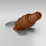
Lately, there have been surfacing some great mini models here. Please take your time to accept my micro (not just mini!) models here as well. Because finally, after half a year of sweating, I can proudly present these micro ships to you . I've been wanting to make these guys ever since my A-wing, to expand my lines of micro SW ships. But it didn"t proove to be easy. [MOC] micro B-wing & Y-wing by Bert.VR, on Flickr I had already built a Y-wing with 5 pieces, but didn't consider that as what I really wanted . So I sat down again to play with all kinds of pieces. The idea of using Technic axles for the columns was what sparked the Y-wing. It also offered a chance to use my favorite part, the wrench. It may look a bit skinny, but at least a sence of greebling is there. The hardest part was the head of the fighter. I really wanted that sloping form, and it had to be thicker than the body (that wonderful SNOT brick). I came up with the frogman's foot inserted in a claw piece. And tada, a 15 part Y-wing is born (16 parts if you would like to add a minifig hand on top to simulate a cannon)! In my opinion, it's much better than the version from the advent calendar... [MOC] micro B-wing & Y-wing by Bert.VR, on Flickr A B-wing had never been featured in the advent calendar (the scale I aim for), and pretty soon I discovered why. To make it look good in this scale, it has to be as thin as a single plate, and studs would completely ruin the model . So I was left with all those specialty pieces. I scrolled through the whole part inventory of LDD multiple times, only to find nothing. The B-wing remained unbuilt for several months. Do you know that feeling when after a very long time, you finally find what you are looking for? Well, imagine the feeling I experienced when, completely out of the blue, I stumbled across THE piece for my B-wing . Recognized it already? The piece that makes the central wing of the B-wing is... It had everything (apart from not being produced in grey) to make my B-wing look good. Some claw pieces, and my favorite wrench part soon snapped into place. The wings were a bit tricky, but I'm satisfied with the minifig neck pieces. The hole in it can be assumed to be that logo on the wings. They're not foldable, but can be swapped out easily with normal 1x1 plates to go to landing mode. The B-wing is my smallest model yet, with only 8 (!) pieces . I hope you can enjoy it nonetheless. It's not buildable in real life, unless you want to paint a Buzz wing. The Y-wing is buildable (hurray!), if you go with regular yellow instead of cool yellow, and pick the technic axles in dark grey. so in fact, you could put it next to my x-wing, or any other micro's you might have. [MOC] micro B-wing & Y-wing - exploded by Bert.VR, on Flickr I hope you like it. Comments are always welcome, as well as suggestions for further micro's. Because Size matters not. Judge me by my size, do you ?
-

LDraw to POV Ray Color Rendering Problem
Horatio-Caine posted a topic in Digital LEGO: Tools, Techniques, and Projects
Sorry to be a pain again, I fixed my last problem as I found a thread with the solution, but there's now another problem that I need some help on. After fixing the color values by using notepad to modify the code by changing the srgb tag on each color to just rgb I managed to render my latest MOC (I've got to say I'm liking the potential I see here when using POV-Ray), however the main color of the model is black, however when rendered, it is a dark grey color, as you can see here. I'm pretty stuck on what it might be that is causing this, no doubt it is something simple probably. Just so you know I am using POV-Ray 3.6. Perhaps upgrading to 3.7 will solve it however I'd like to try and find a solution with 3.6. If it helps as well I have the POV file I can send if someone is willing to render it and compare it to the point where the issue could be uncovered. Many thanks for any help, really hope I can get this sorted as it looks so much more realistic so can't wait to see what it looks like on my past and future LDraw MOC's. -
Hello!! After seeing the Technic Set 41999 in which I found aesthetically very beautiful, I decided to make a replica of it in minifig scale :) is actually a Dodge Charger 1970 with big wheels :) I will build the same physically, there are these renderings This MOC its also on Cuusoo http://lego.cuusoo.com/ideas/view/51928 Full resolutions http://www.flickr.co...in/photostream/ http://www.flickr.co...in/photostream/
-
Another charming digital creation- this time high-res renders of all the current and upcoming Iron Men from TLG, based off official figures. For fans, the shot on Flickr is suitable for an HD desktop, and an Iron Patriot one is forthcoming. As always, comments and criticism are more than welcome!
-
Based on a reallife building in my hometown. Actually the outcome has almost no similarity with it.. Made with LDD and LDDtoPOVray.
-
Was just tinkering with different cockpits for microfigs. Had a feeling that I need to improve and here it is. Hawken-like Mech by The Mugbearer, on Flickr Microfig Hawken-like Mech.lxf Appreciably smaller than any of my previous models, pretty compact. Based on Hawken, one of the best multiplayer Mecha shooters I know. =D Equipped with auto-gun, rocket launcher (Possibly basic TOW launcher from the game) and repair drone
-

[Guide] Rendering LDraw models using POV-Ray
C3POwen posted a topic in Digital LEGO: Tools, Techniques, and Projects
I was asked to put together a tutorial on rendering LDraw-produced models in POV-Ray in as clear and simple a way as possible. Although the following might seem a bit lengthy, I have tried to keep it clear, which is what caused it require a lot of explanation. I plan on updating things and changing things as time goes on and as people give me their input, so as to create a useful guide for everyone here on Eurobricks. NOTE: To give an idea of how long these images can take to render, I will be adding the render time of each image to the tutorial. As I don't rely on POV-Ray's anti-aliasing, I have rendered each image at 2880x1620 with AA set to off, and then crop and resize the image afterwards. For computer spec comparisons, I use an Intel Core i5 running at 2.67 GHz, with 4GB of RAM running at 1333 MHz and an NVIDIA GeForce GTX 460 with 1GB of RAM. I'm also using POV-Ray 3.7, which can take advantage of more than one CPU core. Contents Introduction Requirements MLCad (including LSynth and SR 3D Builder) Special files LDView Setting up POV-Ray Rendering your model in POV-Ray (including lighting and effects) Downloads More information Version history 1. Introduction Unlike LEGO’s own Digital Designer (LDD), which can currently only output an image of exactly what you can see within the LDD window, LEGO models created using LDraw can be turned into high-quality and, in some cases, photo-realistic images. This brief tutorial covers some of the basics of converting files created in LDraw and other compatible programs into something that looks almost real. As an example throughout this guide, I will be using a model I made in MLCad of the tipper from 4201 Loader and Tipper, which can be found here. 2. Requirements Regarding operating system, I currently use Windows 7, so this tutorial will be written to mainly accommodate Windows users, and I shall assume you are using a 32-bit version of Windows with the default installation path for LDraw. For anyone using a 64-bit version, when referencing folder paths please use “C:\Program Files (x86)” instead of “C:\Program Files”. Firstly, if you do not have it installed already, you need to install the LDraw All-In-One Installer, which contains the following programs required for this tutorial: The LDraw parts library MLCad, used for building the models LSynth [optional], a system for building flexible parts within MLCad LDView, used for converting models into a POV-Ray file LGEO, a parts library built specifically for POV-Ray POV-Ray, a ray-tracer that can render 3D models in high-quality You can find the installer here: http://www.ldraw.org/ This will install everything within the "C:\Program Files\LDRAW" folder, although POV-Ray will get its own installation folder. More information on this installer can be found at http://www.holly-woo...w/aioi1-en.html At the moment, the installer seems to install POV-Ray 3.6, but if you're using a computer with multiple CPUs then it would be worth downloading and installing beta version 3.7, as this can make use of more than one CPU. This can be downloaded from http://www.povray.org/beta/ and is installed in the Program Files folder, but installs the "ini" and "include" files in your My Documents folder. Although it's still in beta, I've had no issues when using this to render images. 3. MLCad MLCad is a user-interface for the LDraw system, and makes it easier to create virtual LEGO models than hand-coding the location of each piece. It’s not as straight-forward to use as LEGO Digital Designer, but the parts list contains a greater number of “older” pieces, you ultimately have complete control over brick placement as LDD-style collision is ignored, and (if you’re feeling adventurous) you can even recreate LEGO elements yourself, if they have not been created already, and submit them to the LDraw parts lists. It is missing a number of more recent parts, but new elements are always being submitted and can be downloaded and installed fairly easily. There are many excellent tutorials on how to use MLCad, so I won’t cover that here. However, there are a few settings within MLCad that I use that you may find useful. Firstly, under Settings → General → Change... and then on the Step, Grid, Snap tab, I set the values as below: The coarse settings are left at MLCad’s default setting. The medium settings are changed to 1 unit per step, and the rotation angle is set to mimic the rotation of the new-style locking hinge pieces, which can be set at angles of 22.5 degrees. 11.25 degrees gives you slightly more freedom when using the old-style hinge pieces, but the correct angle is easily set for the locking hinges, which can be reproduced in sets of two rotations. Finally, the fine settings are set very low, so that I can accurately place items that have been rotated. Of course, if you find MLCad’s default settings enough, then they can be left as they are. I then set up the parts tree to something more useable, under Settings → Parts Tree → Tree Configuration…, although this can be quite time-consuming and if you accidentally reset the tree you cannot easily get the settings back, as the information is stored in your computer's registry. For ease of use, I have created a group file that automatically adds the values for you, an explanation of which is available in the “Downloads” section. 3.1. LSynth If this is installed alongside MLCad, it will allow you to render flexible elements, such as hoses, and store these within your LDR and MPD files. It has a bit of a learning curve (pun not intended), but once you’ve got the hang of it, it can really improve models that contain flexible parts. A modest example of what it can do can be found here in a Technic model that I’ve rendered. A good guide can also be found at http://www.holly-woo...utorial-en.html 3.2. SR 3D Builder A lot of people use SR 3D Builder as an alternative to MLCad, as it uses a system that is a little more like LDD. It uses a file format called L3B, which is essentially the LDraw format but with a bit more functionality. These files can also be opened within LDView, but certain special elements created within SR 3D Builder (such as rubber hoses) cannot be displayed using LDView, and therefore cannot be exported to POV-Ray for rendering. As far as I’m aware, SR 3D Builder does not recognise the LSynth library of parts. 4. Special files There are a few special files that are installed with the All-In-One installer which need some adjusting before rendering your model in POV-Ray. LGEO.xml This file contains all of the colour and element definitions for when LDView is exporting a model to the POV-Ray format. The default version is missing some colours, so I have created a more complete version, which can be found in 8. Downloads. Simply replace the default version with this one, and you will have more of LDraw’s colours available to render with. This needs to be saved to “C:\Program Files\LDRAW\LDView” lg_color.inc This file is installed into LGEO's program folder, in the "lg" sub-folder. It contains definitions to all of the colours of the bricks that POV-Ray uses, as well as information on element finish (transparency, reflection, etc.). The default one does not render accurate LEGO colours, so a replacement for this one can be found in 8. Downloads. This needs to be saved to "C:\Program Files\LDRAW\LGEO\lg" 5. LDView Once you have completed your model in MLCad, open LDView and locate the model file (either an LDR or MPD file, or L3B is you have used SR 3D Builder). Depending on how good your graphics card is, you should see a representation of your model that looks better than the one shown in MLCad. As LDView also displays the LEGO logo on element studs, you can use this to check to see if they are set to your desired rotation, as this will carry through to the POV-Ray render. Settings-wise, there is little that needs tweaking here, as it is mainly just for visual effect. However, you can set a better default angle, as LDView’s default is more top-down than the default one in MLCad, and when you export the model to POV-Ray, it will use the angle you currently have your model rotated to. Select View → Viewing Angles → Specify latitude/longitude, and enter your desired values. As I said, I like the default MLCad 3D angle, so I use latitude 23 and longitude 45, although latitude 30 works well with some long, low models, such as cars. Click OK and then go back to View → Viewing Angles and then click Save Current as Default. Now, when you open any model within LDView, it will always be initially displayed at this angle. The model I will be using as it appears within LDView: Render time: N/A 5.1. Exporting to a .pov file Now that you have your file open in LDView, click File → Export. This will bring up a dialog box which allows you to specify where you wish to save the exported file. It also has a button called Options..., which allows you to define various parameters. This is where you can set the aspect ratio for your render, and gives you some specific options: 5:4, 4:3, 3:2, 5:3, 16:9 and 2.35:1. I tend to go with 16:9, as that’s the ratio that modern widescreen TVs and monitors tend to use. It’s important that you remember which one you use, as you will need to set up another file in POV-Ray to account for this. There are a few other options to choose from here, and I use the ones shown below: Once you’ve chosen your settings, click OK and then from the Export window click Save. This will create a .pov file at your chosen location, using your chosen file name (by default this is the filename of the model you were looking at in LDView). 6. Setting up POV-Ray 6.1. Image resolution presets The first thing to set up is the file that contains the default resolution presets. If you are using POV-Ray 3.6, this will be located within the “C:\Program Files (x86)\POV-Ray for Windows v3.6\renderer” folder and will be called “quickres.ini”, and this cannot be edited from here, so you may need to copy the file to your desktop first and then open it from there. If you’re using POV-Ray 3.7, this can be edited within the program itself, as it stores it in you user area, so you can just open POV-Ray and select Tools → Edit resolution INI file. Open this file with a text editor and you should be able to see a list of screen resolutions, listed in this format: [1280x1024, AA 0.3] Width=1280 Height=1024 Antialias=On Antialias_Threshold=0.3 The first line is the name of the preset, and this is displayed in a drop-down box within POV-Ray. The following lines are the actual settings themselves. Copy and paste one of these settings to another location in this file, so we can create a new preset. You can leave both Antialias and Antialias_Threshold alone, as these are best left at default. If you wish to create an image that matches the aspect ratio set within LDView, this is where you set it. As I prefer to render in 16:9, then I need to make a width and height that matches this. So, for example, an image that is 1280 pixels in width must be 720 pixels in height, so you need to change this for your new preset, resulting in something like this: [1280x720 16:9, AA 0.3] Width=1280 Height=720 Antialias=On Antialias_Threshold=0.3 I add the 16:9 comment to the preset’s title, just to make it easier to see the ratio. If you’ve had to edit this from your desktop, then just copy it back to the original location. 6.2. POV-Ray INI file (3.7 only) This file is the one that contains the paths to the LGEO pieces that POV-Ray utilizes in rendering. If you’re using POV-Ray 3.6 it should already have the right paths in it. However, if you’ve manually installed the POV-Ray 3.7 beta, then it needs to be set up. Open POV-Ray and go to Tools → Edit master POVRAY.INI, and this should open the file within a text editor. At the bottom of the file, you need to insert three lines to ensure that POV-Ray can locate the right files. These are: Library_Path="C:\Program Files\LDraw\LGEO" Library_Path="C:\Program Files\LDraw\LGEO\ar" Library_Path="C:\Program Files\LDraw\LGEO\lg" Don’t forget that if you’re using a 64-bit operating system to make sure that the path uses "C:\Program Files (x86)".