Search the Community
Showing results for tags 'Tutorial'.
Found 95 results
-
And a short video to showcase some of the most interesting parts of the construction Racing version
-

About the Wedo 2.0 open project Tutorials
sube posted a topic in LEGO Technic, Mindstorms, Model Team and Scale Modeling
Hellow everyone ! I'm new here. I just want to ask if anyone know that where I can find any tutorial video or webpage of the “open projects” in Wedo 2.0. I just can find some advertising videos about Wedo 2.0 online. Thanks a lot! -
Octan delivery VAN with smooth body lines and good cargo capacity >> How to build video >> http://www.youtube.com/watch?v=www.youtube.com/watch?v=zxXrOMP_MXc Thanks for watching!
-
I will let the pictures do the talking >>> + a video tutorial how to build one Yourself http://www.youtube.com/watch?v=www.youtube.com/watch?v=va26M29tGCE Thanks for watching! #keeponbricking !!!
-
Hello everyone! As nobody else seems to be interested in making a tutorial for building masts, I'll have to do it myself! If you happen to have more techniques for making masts or just want to thank me for it - off course only after reading the full tutorial - go ahead and either show them or do what you think is necessary! This topic is just about building the masts, not the ship, ship, sails, sails, sails or the rigging, all those have separate topics. If you feel like there is something missing from this topic just tell me. Edit 1: Further tricks to stabilise connections between mast sections by Ejred: click here So, lets start: Lets begin in the year 1989. The Black Seas Barracuda just got released. It contains some interesting pieces, which I'll show first: Some of these parts were released later, but still fit well with these masts. Lets see what one could do with these masts: One could simply combine the different Mast sections, or: Stack them above each other. Could also be combined with another technique I show later on. Then there are the new Mast parts - first released with the 4+ Pirate ship which can also be combined with other techniques: And, as expected, one can just stack these above each other: I'll not show more of these, if anyone wants to show all the possibilities these give you go ahead! Now, on to parts that are useful to custom Mast building: Technic axles. There are also a 16 stud long one and a 32 stud long one, I didn't put those on this picture though. Technic bushes. All kinds of them. These can be combined to form the upper part of a mast: Just lengthen these sections and put them ontop of your bottom mast part - or use them where ever you see them fit. If you want to reinforce the round ones you can use flex tubes: Which are available in many colours and length, but they are, as the name suggests, flexible. Other parts that can be used for masts are these: I'll go into more detail with the 2x2 and 4x4 round ones now, as those are the most interesting ones for the biggest part of the mast. One can use a 32 long technic axle to get a decently sized mast going. But what if that isn't enough? Or maybe that is not exactly the length you want? Then the next part might be the solution for you: For this example we'll use two sections of 15 2/3 studs height and 3 platforms; this technique can be applied to any sensible size. I recommend at least two platforms to make it sturdy though. As you can see a 32 stud long axle is not exactly fitting for this kind of mast - the mast would just break of right above it. So, you ask, what do we use instead? Flex tubes? Those are both flexible and not exactly cheap to acquire in decent length - and you might even have to cut them. No, we'll use this instead: You need some round 1x1 plates in a colour that doesn't clash with your existing design, a pair of scissors (which won't be used to cut pieces nor will it be build into the mast), a technic pin, a technic axle of your choice (I'm using an 8 stud long one here, but you can use any length you like and a bit of string with a diameter of around 1mm. Warning! If you use this technique the technic pin and maybe one of the 4x4 round bricks with technic holes might be damaged. Next you take a bit of string that is a bit longer than your mast: I've taken a bit to much here, but rather take to much than to little. Next, you tie it to the technic pin: It just needs to be tied around in a way that the string won't move away if you pull on the string. Then you just pull it through your mast: Note: the technic pin is at the upper end, not connected to anything, just hanging there. Now you put the mast back together and pull the string tight. Next we use the technic axle to fix the string at the bottom and also give us a way to mount this mast really securely in our ship. Don't cut off the remains of the string just jet. While pushing the technic axle in, pull a bit on the string. Now, the part which might hurt some of you: You have to pull the string (which you just tightened with the axle) around to insert the technic pin into one of the pin holes on the round 4x4 brick with pinholes. Don't losen the technic axle for this, the string is a tiny bit flexible which should still allow this. Now that we've done this, it is time to check if this mast is already strong enough for our course: Well, this isn't strong enough for me(it might be for some of you - this already takes a bit of force), so lets go on and use some of those round 1x1 plates that I said to have ready: You see this gap? That is where you'll place your 1x1 round plates. It doesn't exactly matter if you go side by side or around, just place 4 of them. It should look like this now: In my case, this was sturdy enough. If it isn't in your case, just add those plates to the top platform too. Note: There are alternative solutions to the technic pin; for me it is the easiest solution - especially as both parts at risk are quite cheap. I've given some examples at how to built the upper mast, but if you feel like adding more examples go for it - I don't know everything about masts either. Also, excuse the bad lighting in some of these pictures - I hope everything is still well visible.
-
Hi togehter, when I am selling Lego ships (I buy them and sell them expansiver to finance my collecting hobby) I wrote in the text that I cleaned the sails and that they are now like new. And every time 100 persons wants to know how I make that. Because of that I made a youtube video with my wife. It is nothing professional but it is enough to learn how it works. German with English subtitles German
-

[TUTORIAL] Modify your LEGO Tires for Performance
DamonMM2000 posted a topic in LEGO Technic, Mindstorms, Model Team and Scale Modeling
This tutorial shows how to increase the firmness of your LEGO tires! If your Mindstorms or Technic creation is pushing the tires down like a flat tire due to heavy weight, or if you want less rolling resistance from squishy tires, you've come to the right place! I hope this tutorial is a big help! NOTE: You will have to search around for the right size, depending on the tire. One size does not fit all. Typically, foam inserts from 1/16 scale RC vehicles should fit on tires from 42000 Grand Prix Racer, 8110 Unimog U400, or 9398 4x4 Crawler. -
 ...
... -
This is a tutorial detailing how to modify a LEGO 9V train motor so that it may be powered independently of the track. This effort is part of a larger project inspired by Thorsten Benter’s article in Railbricks Issue 7 titled “PF and 9V Trains: The Best of Both Worlds”. Step 1) Open the 9V motor. This has been covered elsewhere, so it should suffice to say you carefully remove the 12 tabs holding the bottom cover on with an xacto blade or something similar. There is enough friction to hold the bottom cover in place later even without the tabs. Step 2) Remove all internal parts. Ignore the fact that I took this photo after completing step 3. Step 3) Use a rotary tool with a cutoff disk to bisect the metal strips in the top of the motor enclosure. These strips are exposed in the top studs, and we will later use them to pull power from the track and apply power to the motor. Very important: Be sure to apply NO PRESSURE when using the rotary tool. Instead, just lightly touch the spinning cutoff disk against the metal strip, and let the tool do the work. It will take some time, so be patient and careful. If you apply pressure, the metal strips will heat up and deform the plastic. If the plastic deforms, it will be impossible to interface with LEGO bricks and PCB adapters (like the one in the upper-right corner of the picture). Keep it light and easy. You will thank yourself later when you haven’t ruined your motor’s plastic housing. Step 4) Desolder the metal pieces from the electric motor. I don’t have a picture of this exact step because I used the electric motor from a Power Functions train motor. If replacing the 9V motor with a Power Functions motor, open up the PF train motor using a T6 bit, remove the electric motor, and desolder it from the wires. Step 5) Solder a short length of wire to each tab on the electric motor (do this outside the housing to avoid accidently melting it). I used 32 gauge DCC decoder wire, but you can use whatever you have that will fit inside the motor. Reassemble the motor with exception of the wheels and the bottom cover. Step 6) Attach the wires to the outermost halves of the metal strips; the innermost halves are connected to the wheels through the wipers. I used a silver epoxy for this. I chose silver epoxy for two reasons: 1) I didn’t want to risk melting the studs by soldering the wires to the metal strips, and 2) silver epoxy has a lower resistance than graphite epoxy. Step 7) Reinstall the wheels and make sure everything is running smoothly. This would also be a good time to lubricate the gears if you want to. Make sure you don’t get any lubricant on the electrical parts! Press the bottom cover onto what remains of the tabs, and you’re done! If you ever want to run the motor directly from track power, simply use a PCB adapter with a loopback connector or connect a LEGO wire (9V or light gray end of PF). This is what a PCB adapter looks like when installed on the motor. (I’ve updated the design since taking the previous photo.) And here is a connector leading up to the electronics (currently just a Power Functions battery box, soon to include a Bluetooth receiver) in my Horizon Express. The connector plugs into the PCB adapter. The PCB adapter is attached to the electrical studs on the motor. And the motor is pinned to the bottom plate of the locomotive. Now I can charge the battery in my train without taking it off the track, run it indefinitely on a mixed metal and plastic layout, and have non-line-of-sight control when I add the Bluetooth receiver. It really is the best of both worlds!
-
Hey guys! I'm a Blender artist and I just wanted to share some resources here. With this videotutorial series you'll learn how to create 3D Lego art! Final Result:
-
Tutorial https://www.flickr.c...../<br /><br />
-

LDD animating tutorial 3: Grouping and rigging
Zerobricks posted a topic in Digital LEGO: Tools, Techniques, and Projects
As promised here's the third tutorial where I talk about how to group and move characters in order to animate them. This is my longest tutorial yet, it took me one day and half a night to make, so any feedback would be nice... Files: http://www.bricksafe...ating tutorials I challenge you guys to use te provided files and try making a simple animation. Thanks! -
LDD animating tutorial 2: Character and model design
Zerobricks posted a topic in Digital LEGO: Tools, Techniques, and Projects
Here's my second LDD tutorial, this time concentrating on how:to create models that are appropriate for animating purposes. You can download the LDD and image files here: http://www.bricksafe...ating tutorials P.S. Aint she cute? -
Flickr seems to change so often that it's hard to keep up with all of its functions. There have been a number of questions about deeplinking from Flickr recently, so I hope people find this short tutorial helpful. I have included TWO ways of sharing pictures from Flickr in this tutorial; using the "Share" button and through the "Download" button. Embedding pictures using the "Share button. Embedding pictures using the "Download" button. Feel free to post questions about Flickr here and anyone can answer them. For any other questions, ie anything not relating to flickr, please check the FAQ tab in the upper right of the forum, or post in the HELP! ! ! topic here in Forum Information and Help.
-
How to apply custom decals on LDD renders
BEAVeR posted a topic in Digital LEGO: Tools, Techniques, and Projects
You may have encountered it: you built a nice model in LDD, but it looks surreal because it lacks decorations on e.g. the minifigs. This tutorial is here to help you with that. In this little tutorial, I will try to explain how you can enhance the POV-Ray renders of your LDD models with custom decorations. You can design entirely new figures for example, or you can apply the decorations that aren’t available in LDD. My example in this tutorial will be a stormtrooper minifig. This figure lacks all decoration in LDD, and is commonly used in digital Star Wars builds. It gives me the opportunity to explain how to decorate surfaces that aren’t directly accessible in LDD, how to fit custom decals and explain the general principles. This method doesn’t involve any hacking and doesn’t require any sick programming skills (although the custom decorations might need your artistic talents…). And the best of all: all programs I use here are entirely free! I’ll be using Lego Digital Designer, LDD2POV-Ray, POV-Ray and Inkscape. So let’s get started! Decorate the target pieces in LDD LDD2POV-Ray, the program that will eventually place your custom decorations, can only replace already applied decorations. So firstly, you need to give the pieces you want to decorate a replacement decoration in LDD. Make sure to use different decorations for each surface, so that you later can keep track of which filler to replace with which substitute. Also, taking a screenshot for reference is not a bad idea to support your memory. But wait a minute… Some parts don’t allow for any decorations at all in LDD! Minifig torso’s are not a problem at all, but things like helmets are a whole different story. But luckily, there is an easy way to apply decorations that will work in most cases (no guarantees though!). You have to export your .lxf file to the LXFML format (File -> Export Model). This .lxfml file is actually a textual representation of your model. Among others, it contains a list with the placed parts, including their color(s) and decoration(s). To find your part, use the search function (Ctrl + F / Cmd + F) and type in: in which you replace 30408 (the designID of the storm trooper helmet in this example) with the designID of the part you desperately want to decorate. You can find this ID by clicking on the part in LDD and looking at the bottom left corner. If multiple of these parts are available, you can give the specific part a different color and check for the one that says materials=”26” in which you replace 26 with the number of the color you used (you can find this number by hovering over the color in the color menu in LDD). The key part is then to change the part that says decorations=”0,0,0” in which the amount of zeros dictates the amount of surfaces that you can decorate. If the line isn’t present at all, you’re out of luck and won’t be able to decorate your part. Otherwise, replace the zeros with valid decoration ID’s. It’s best to take decorations that are square and detailed (I will explain why later), so I suggest using the decorations of the 2x2 flat tiles. You can find these ID’s by placing some of these decorated tiles in your model, and check in the LXFML file what number is filled in in the decorations line of those parts. To make it easier for you, here are some handy decoration ID’s you can use: 73023, 63708, 99825, 55350, 63404, 601245 Then, save your file, and open it with LDD. You’ll see your parts are looking very ugly with those random decorations, but you’ll be happy to have decorations. You can copy these parts to a ‘normal’ .lxf file, and get rid of the parts you used to find the decoration numbers. Now we can move on to step 2! 2. Open your model with LDD2POV-Ray LDD2POV-Ray is a program that converts your LDD model into a file that can be rendered with POV-Ray, a ray tracer that simulates the behaviour of real light to simulate a realistic effect. You can set lighting etc, but more importantly, you can set your own decorations. To do this, go to the “Decorations” tab, and check the box “Use custom decorations”. A list will appear at the bottom, showing all the decorations you used. Clicking on them will reveal a thumbnail. Now you’ll be happy that you used different decorations to know which is which. You’ll notice that the decorations (unless they are square) are a bit stretched out. That’s because the program only accepts square decorations. So to load your own decorations, you’ll have to make sure they are square. Otherwise, they won’t cover the whole area you intended. If you already have your decorations (you found them on one of the indexes of the customisation forum here, for example), you can skip to step 4. Otherwise, I’ll give a brief account on how to make your own decorations in step 3. 3. Create your own decorations Personally, I make my decorations with Inkscape. It’s an easy to use vector based program. That means you can easily create very clean, smooth and crisp shapes. I’ll leave it to others to educate you in this nice software, but I’ll show you some general strategies to make accurate decorations. When working on complex curved shapes, like the storm trooper helmet, you won’t know for certain how your image will be mapped to the surface. That’s when the screenshot you took comes in handily. Because you have used decorations with a lot of detail (if you’ve been following properly!), you can easily see how the image is deformed and placed on the surface. You can identify the regions where you want your details to come, look to what part of the placed decoration it corresponds, see what it looks like in its flat state (you can see this in the thumbnail in LDD2POV-Ray), and place your detail in the according place. So in the example of the storm trooper helmet, you can see that the mouth should somewhere at the center of the graph. LDD2POV-Ray shows that that graph is a bit above the, so now you know you have to place the mouth around the center of your decal. When you’ve finished your decoration, you have to make sure your decoration is square. This will most certainly occur when you’re designing decorations for minifig torsos. If you leave it in its actual proportions and plug it in LDD2POV-Ray, you’ll see that the image doesn’t fill the whole area, compared to the stretched out decoration you have to replace. So you resize your decoration. In Inkscape, simply go to the top, where you can enter dimensions. Then you go to File -> Export Bitmap and a dialogue box will pop up. Make sure to select ‘from selection’, and that the amount of pixels of your image is high enough. Otherwise it will look pixelated in the render. Finally, chose .png as file format, and remove the background color of your decoration. Because it might look like the right color in Inkscape, but in your render it will look like the decal has a different color than the body, which isn’t what you wanted. So now you have your parts temporarily decorated, and you got your custom decorations ready. So time to replace them and render them. 4. Render your decorated model Firstly, you have to load your new decorations in LDD2POV-Ray. There are multiple ways to do this, but the easiest method is to select the decoration you want to replace and then click on the empty canvas. A window will pop up to allow you to select your decoration. Just select it. Repeat for the other decorations, making sure you replace the right decoration with the right replacement (that screenshot will come in handy now, especially since you can’t have both LDD and LDD2POV-Ray open at the same time at this moment!). Then you can fiddle around with different settings like lighting etc. For test renders I suggest to place in the first tab the slider on the lowest positions: ‘LDD geometry’. This will result in slightly less good, but much faster renders, allowing you to quickly get feedback about your decorations, so that you can adjust placement and proportions. For flat parts this won’t be necessary, but it can help for curved parts. That’s why I included the TIE pilot in the render. You can see the ensignas are slightly deformed. That’s not my intention, but I already predeformed the circles in the decal, so that it looks more or less round on the surface. You’ll have to experiment a lot with these ones. Anyway, when you're satisfied and feel the need for a more glamorous render, you can turn 'render with visible bevels' on in the slider bar, and wait for some time. You'll get something like this. Hopefully now you know all about rendering your custom minifigs, making your models more realistic. I hope to see some around! Anyway: happy rendering of your minifigs! If anyone is interested in downloading the decorations I designed for the stormtrooper (for now without back printing) and the TIE pilot (torso printing already present in LDD), have a look at this page. Hope you've found this useful. -
[pid][/pid] This tutorial has been sitting on my computer for ages and I only now decided to finish it and along with another project, end my micro-dark age. It’s about a piece of equipment almost as important as the ship itself: the European cannon. Please notice that while I do know a good deal about Asian Cannon and early Asian rockets I will not cover them in this tutorial! PART I – basics, material and history Cannon (from lat. Canna - “reed”) are projectile-launching weapons that were first used in the Far East and came into use in Europe during the High Middle Ages. It was the first gunpowder weapon on battlefields to be used at a large scale with effectiveness above that of a psychological impact. Although Cannon greatly varied over time and purpose in shape, composition, material, carriage and performance they still shared very distinctive features over hundreds of years. Cannon are always tubes made of metal that are mounted on a carriage (“Lafette”) and are almost always loaded via the muzzle. A gunpowder charge will be embedded between the thickest part of the cannon (the reinforce) and a cannonball. It is ignited by a fuse or a mechanism that is accessible via a small vent. The standard projectiles of cannon first were made out of stone, later metal. It quickly became common to classify cannon according to the type of projectile they could fire rather than the appearance of the actual cannon itself. A 12 pounder (a cannon capable of firing cannonballs that weighed 12 pounds) could look completely different in comparison to another 12 pounder just because one of them was being used on a ship and the other one on the field. Cannon came into use in Europe around the late 13th and early 14th century. The first major war to feature effective Cannon made of iron was the Hundred Year War. Most cannon, however, were being made from bronze at the time as this was a much more durable and reliable metal. With the propagation of improved cast iron (especially in England) in the late 15th century the European cannon got yet another material improvement and by the late 18th century almost all cannon were made from cast iron. European vessels were being equipped with cannon from at least 1330. However, designated battleships with sails came not into use until the early 16th century when the English Navy started constructing men-of-war specifically built for carrying large amounts of cannon. The first recorded purposely built gun deck was built around 1500. Until this time it was much more common to refit merchant ships like carracks, cogs, galleys and caravels into war ships if the need arose. Around the middle of the 16th century most European armies began standardizing their cannon size according to the aforementioned weight of the projectiles. Improvements in the gunpowder used and the quality of the structure of the bore allowed for smaller cannon that were actually mobile and allowed for much quicker advancing armies that could still fire over great distances. This development of siege possibilities also greatly changed the methods employed to construct fortifications (see the development of fortifications in this tutorial). While details such as transportation (limbers), aiming (trunnions) or better projectiles (cast iron projectiles) continued to increase the effectiveness of cannon they remained largely the same during the next few hundred years with the only notable exception being the mortar – a cannon designed to fire projectiles over large distances and send them across fortifications. Major change to the cannon was brought by the massive development of men-of-war in the 18th and the 19th century. The introduction of the carronade in the late 18th century supported quicker and more manoeuvrable ships: smaller, lighter Cannon being able to deliver 32 pound ordnance on short range that was able to virtually pulverize the hull of an enemy ship. Gunlocks drastically improved the speed, safety and accuracy of quickly loaded, hot cannon. In addition to improved accuracy and firing rates, new ordnance types (shrapnel shots and reliable explosive shots) brought new elements into field- and sea battle. The introduction of steel-Cannon in the mid-19th century made way for the demise of the classic cannon: although still being used until the early 20th century the cannon would eventually be replaced by steel-made field artillery and recoilless guns. PART II types and calibres This part of the tutorial will focus on cannon that were in use after the ordnance classification system had been well established. While a lot of basic cannon types will be described keep in mind that there have been well over 70 types of cannon in Europe alone and hundreds of specialized cannon series. Sakers - 4–7 pounders Sakers were relatively light cannon used en masse during the 16th century. Made from bronze they were designed for long range attacks against moving armies or fortifications. The early models still used stone ammunition but all later versions used the more modern iron ammunition. Sakers were very heavy and relied on a stable and heavy carriage due to the immense recoil the large gunpowder charge caused – thus they were used from fixed positions and were not moved during a battle. Culverins – 14-20 pounders Also used on sailing ships (merchant ships, men of war) Culverins were used from the middle to late 15th century until the early 17th century. They were made from bronze and featured a very long and thin bore (up to 5 meters) that could fire very different types of cannon balls. It was one of the first cannon to be successfully mass-produced and was able to fire cannon balls made from iron. A culverin was operated by between three and five gunners and was normally being transported on the mobile carriage with or without a limber. Mortars – 82 – 180 pounders Also used on sailing ships (bomb ketches) Mortars were used from the middle 15h century till the end of cannon. They featured a very short and large bore that looked more like a bowl than a barrel. Mortars had a high trajectory allowing for large range and the possibility to attack an enemy behind a fortification. The low velocity of the projectile also allowed for explosive rounds to be used. A mortar could be operated by two to four gunners and was very immobile due to the immense weight of cannon and ammunition. Full cannon – 42 pounders Also used on sailing ships (ships of the line) Full cannon were used during the 17th century and were normally made from cast iron. If they were to be used on a ship the preferred material was bronze in order to keep the weight lower. They were designed to take down heavy fortifications and to engage slowly moving targets at long range. On ships they were used on the top battery deck as the back bone of close range broadside attacks. Full cannon were immobile on the field and considered to be impractical due to large gunner crews of 5 to 9. Demi cannon – 32 pounders Also used on sailing ships (ships of the line, frigates) Demi cannon were used in the 17th century as a semi-accurate and close range cannon that was usually made from cast iron. The cannon required a gunner crew of at least 4 persons and would normally be used to attack advancing armies with regular shots and grapeshot attacks. Demi cannon were largely immobile due to their weight. Minions – 5 pounders Also used on sailing ships (all types of ships) Minions were the weapon of choice for close range anti-personnel attacks in the field and on ships. The small cannon was used from the 15th century till the early 18th century and could be seen as a “big brother” of the swivel gun. Minions could be carried by mobile carriage or by the gunner crew that could be 1 to 3 people. Minions were considered to be highly mobile weapons that could easily be used to defend advancing points during a battle. Howitzer cannon – 12-24 pounders Howitzers were a hybrid between regular cannon and mortars, being used from the late 17th century till the end of the age of sail. The Howitzer was mobile and could be quickly adjusted to various angles, making it a somewhat inaccurate but fast and flexible siege weapon. The Howitzer could fire a great variety of different ammunition, making it efficient in use against fortifications and army formations. A Howitzer was being operated by a gunner crew of three to 6 persons, depending on the size and the purpose of the Howitzer. Howitzers were mobile but larger versions could be difficult to move during a battle. Carronade – 6-42 pounders Mainly used on sailing ships (all types of men of war) The carronade was an immensely popular naval cannon presenting the complete range of cannon sizes. A short bore and a smaller charge chamber would fire a low velocity cannon ball with a short effective range. The low speed would damage the hull of the enemy and the deck behind it much more than high velocity ammunition. The carronade was being used from the late 18th to the late 19th century. While the short range did only allow for passing fights the high speed of the reloading process, the devastating damage and the small amount of gunners (2 to three) needed made it a perfect cannon for fast ships or ships of the line. PART III carriages, casemates and additional equipment As diverse as the cannon types were as diverse was the equipment used with them. Carriages featured large or small wheels, four or two wheels and very often no wheels at all. They would normally be transported with or on limbers that was also used to carry ammunition, cleaning equipment, aiming aids and so on. A single Culverin with equipment could need up to 4 horses to be transported. Many cannon featured different styles of trunnions that could be used to change the firing angle by adjusting the height of the muzzle. Cannon were also used in fortifications. They were often positioned on the top or within casemates. These cannon could feature very innovative carriages that were designed specifically to be able to quickly adjust the firing angle in order to compensate for the inability to move the cannon. Thank you for reading all the way down here! No go enjoy the lxf-file on cannon in LDD!
-
I've recently come out of my Lego "dark age" and started rebuilding some of my old sets. I was never one to keep sets together very long, so naturally i've lost a lot of stickers. One of my other hobbies is classic bicycles, which often share the dilema of missing or damaged art. This method for producing decals was taught to me by a clever artist on a popular bicycle forum, so he really deserves any and all credit. This method is simple and inexpensive and much of the materials are common. I assume the trickiest part for most people will be producing the art. I happen to have Adobe Illustrator at home, so I am able to create my own vector art files. I believe other cheap, maybe even free software exists. Sometimes high quality art can also be found as images on the web. On to the step-by-step: 1) Produce the art. Use a laser printer and any cheap printer paper. Laser printing is key... if you don't have one, you could try any of the copy shops around. As mentioned, I used Adobe Illustrator. I am replacing the decals for 6594 Gas Transit. DSC04389 by mkeller234, on Flickr 2) Cover the art with packaging tape. DSC04390 by mkeller234, on Flickr 3) Burnish the tape onto the image. I use scissor handles and rub over the tape surface. You will be able to see which areas have bonded well. It doesn't take much effort. DSC04391 by mkeller234, on Flickr 4) Cut the decals out. The closer, the better. I usually follow the shape of the art, but it doesn't really matter. DSC04392 by mkeller234, on Flickr 5) Submerge in water DSC04393 by mkeller234, on Flickr 6) Once the paper is saturated, it can be rubbed away with light pressure from your thumb. Remove as much paper as possible. DSC04394 by mkeller234, on Flickr As you can see, the decals are clear. This is both a blessing and a curse. I happen to be positioning these over white bricks, so the colors will look nice. For use with dark bricks, you will need to either paint the back with white paint, or find a printer that can print white (ALPS). DSC04395 by mkeller234, on Flickr 7) Place the decals on your model. These decals are very forgiving and can be slid around easily. They stick on their own without glue. Make sure you allow them to dry completely before really handling them. 8) Admire your work! DSC04399 by mkeller234, on Flickr DSC04398 by mkeller234, on Flickr Ahhh... the teeth marks of my youth. DSC04400 by mkeller234, on Flickr Lego trucks sure have changed since I was young. I love the detail in these new models! DSC04401 by mkeller234, on Flickr
-
-
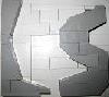
[bloggedcp][/bloggedcp] Hi all, this is my first post here so I hope some of you will find this useful. I have been interested in lego pirates in particular since I got my first set almost 20 years ago. The problem is that as the sets age, the sails become tattered and worn, and can be quite difficult to find. I've been searching for a while now for a reliable technique for reproducing lego sails in as authentic a way as possible, but with little success (maybe I've just been looking wrong?) Anyhow, I've been working on my own technique, and decided I would share it for those who, like me, have been searching for a way to make authentic looking lego sails that are nearly indistinguishable from the originals. The sails I've been working on are those of the Skull's Eye Schooner, the number one ship on my, and half the planet's, wanted list. The problem everyone has when it comes to reproducing sails is trying to work out the material that lego uses. It has a relatively unique stiffness for a cloth that is relatively thin; this is not because a special material has been used, but because a standard linen cloth has been prepared with a sizing/priming agent. What I have done is primed regular calico cloth with a watered down acrylic gesso. When dried, it is a very good likeness of lego's cloth, and is stiff enough to be fed into an inkjet printer. Here's the gesso I used: gesso is used by artists to prime canvases for painting and can be purchased from any art/craft supply store, this jar cost me $10 and will probably make a few dozen sails. They can come coloured, I've chosen white as the base colour of the skull's eye schooner is white, but acrylic paint can be added to make different base colours, such as the tan coloured imperial flagship's sails. Again, just plain calico, very cheap I've cut it slightly larger than A4 here You want to water the gesso down roughly 1 part gesso to 3 parts water, this will help the gesso to soak into the calico. Give it two coats on each side then hang it up to dry. Once dry, I trimmed it down to A4 size. Next up, I got the 1:1 scans from the sails library here: http://www.eurobrick...showtopic=10076 , traced them in photoshop and recoloured them to improve the saturation once printed. As the scans were 1:1, no resizing was needed before printing. I just fed the canvas into the printer carefully and printed at high quality settings. Once the sail is printed it's just a matter of cutting them out: And here's the final result: And here's an armada flagship sail I made I hope someone finds this useful. I will upload my tracings later for anyone who's interested
-
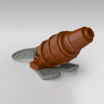
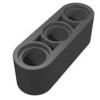
[pid][/pid] Capstans Welcome at my first tutorial here at Classic Pirates, in this tutorial I will try to convince you that there is no argument not to have a functional capstan on your ships. (On condition you have a ship big enough to support one ofcourse and I heard some people are allergic to Technic so I guess that's a valid argument as well). This working capstan design applies perfectly for a frigate in CGH style. I will use a prefab hull for this tutorial but I want you to keep in mind that it can easely be applied to costum hulls as well. This guide will be quite basic because there just are so many different ships, every ship needs its own approach on how to integrate a working capstan. I will start with a simplified construction of a capstan used to haul a singe anchor, then I will extend to more complex and versatile mechanics to eventually allow you to operate two independent anchors. So without further ado, let's get this party started. Operating 1 anchor: You'll need a capstan, it doesn't have to be this one but make sure it connects to a cross axle. But if your really want this one... Another capstan: By Phred An anchor with a winch (also cross axle based). You can use the capstan for other things besides the anchors as well but I'll get to that later. Some usefull technic parts; This is a useful construction; But if you don't have the black part you can use this alternate construction; Now... The implementation of a working capstan takes place at the very beginning of the ship-building process. It's important to place the capstan at the best location of the ship. When starting a new ship I usually start by marking the locations of the masts (I covered them with green round plates to make them more visible). Yellow marks the possible locations of the capstan, keep in mind that the capstan has a volume too so you'll have to reserve some space near the masts. To decide where you will ultimately place your capstan you should consider what else you want in your ship, a staircase and grates perhaps. AT this point you have to know (more or less) how the deck will look. Personally I find it most practical to place the capstan just behind the second mast (on a three mast ship that is), that way I have plenty of room for grates between first and second mast. What I'm going to do now is probably not historically accurate. I will not connect the anchor winch directly to the capstan. I do this for practical reasons, you don't want anchor cables running through the ship, trust me. What I'll do is much more reliable, the anchor winch should be placed as close to the bow as possible (as close to the place where the anchor will hang from the ship), this way there's less chance of complications with rope/cable getting stuck within the ship. Instead of a direct cable connection I will make use of a flexible axle. First attach the capstan to the construction mentioned earlier (this is temporarely, you can detach it later to work on the deck and so on). Then you place this construction in the ship on the place you wanted the capstan (the main reason to attach the capstan already is to make sure it doesn't interfere with the masts). As you can see the capstan is connected to an axle running through the ship. Technic bricks are useful to run through the masts and other obstructions. You may wonder what's the universal joint is for, I noticed some of my ships tend to bend a little when building larger, the joint assures a smooth axle turning. Now the anchor can be hauled up using the capstan. Operating 2 anchors independently: Now in order to provide multiple independent functions to one driving axle, operating two independent anchors with one capstan for example, you'll need a mechanism to shift gears. LEGO Technic provides us with a very easy-to-use system consisting out of these key-parts: Clutch gears: Gear 16 Tooth with Clutch (you need atleast 2). Driving Ring: Driving Ring (you need 1 for each pair of clutch gears). There's also a technic switch available which makes it easier to make the driving ring hatch into the clutch gears: Changeover Catch But I've seen multiple alternatives for that part at the Technic forum, still, I like to use this part over alternatives. In this picture you see the left gear clutched to the axle on top, neutral in the middle (no gears clutch) and right gear clutched at the bottom. connecting the clutch gears with other gears allows you to operate multiple axles, I will now integrate this system in the hull; Note that I just picked a random position of the 'gearbox', you can easely place it practically anywhere, in front of/ after the capstan, in the bow (like I did for my Frigate. Again it's important to think about how your ship will look and what features it will have when choosing a location for the gearbox (The switch was taken out for a better view) The red axle connectors are used to block the gears in one direction, this allows you to pull an anchor while preventing it to fall back down. This isn't always needed though, usually, because the official anchors are so light, the friction alone is enough to keep them up. I used yellow axle connectors to show how to operate the switch, as you can see the lower one allows a rotative motion to switch gears, this means you can attach this end to another flexible axle and thus move the location of the switch away from the gearbox. To illustrate how it works I made this short video: UPDATE: 21 December 2013 The previous construction was built very symmetrically so it would be easier to see how it works. However, when applied to a real MOC ship you don't need to see how it works, the more compact you can build the mechanism, the more space you gain for interior and/or other functions on your ship. I have therefor applied this capstan mechanism to a current WIP of mine to show a more practical example. This is a three-mast ship, the capstan is located after the foremast (very common location for the capstan on a historical ship). The capstan itself will be mounted on the brown vertical axle. The red axle connectors with gray axle towballs are used to block the anchors in place (so they don't fall down after you hauled them). As you can see the gearbox for switching anchors does not lay in line with the ship's length this time. The switch itself is concealed under the yellow technic plate and will be operated by turning the light grey axle. I intend to attach a barrel to the switch axle to hide it on deck in an elegant manner. On this picture you can see the anchor blocking mechanisms, these are connected via several gears to the previously mentioned axle towballs, which will be accessible on deck. Sigh, I really don't get it, when I watch the movie on my camera it's great but when I upload it to my computer it becomes dark . So, this was it, for now. It's my first tutorial so ofcourse it's not perfect, any suggestions to make it better are welcome as well as questions (which may inspire me to expand this tutorial or explain part in a different way). Combine this tutorial with Build a frigate with Captain Green Hair! An interesting link for more about capstans; Capstan by Foremast Jack - - - - - - - - - - - - - I will expand this tutorial later with a sollution for modular ships (yes, a modular ship is not a valid argument not to have a functional capstan so if DPW is reading this... ).
-
GBC Android Counter V1.5 - App,LDD & Tutorial
LegoGBC posted a topic in LEGO Technic, Mindstorms, Model Team and Scale Modeling
After the success of my previous GBC Counter module, I decided to upgrade the app and also release it to the public along with a detailed tutorial for building your own GBC counter. How it works explained here: http://www.eurobricks.com/forum/index.php?showtopic=83844 The app & module support the GBC standard of 1 bps. New features: -Balls per second display -The new app & module can handel more bps than the first version -GBC timer -Better design Tutorial download (includes a PDF file, LDD file and the app itself) http://www.mediafire.com/download/wmfxy3ny1rbdrtc/GBC_Counter_Tutorial.rar The video: Thanks for watching! -
Hello everyone! Kooberz here. Recently, I was asked to create an interview/tour interview for the Red vs Blue Uk event held on August 2-4 in Leicester. They provided the questions, and I did my best to answer them in the best way, and present some of my best and previously unseen work. I hope you like it! Also just released, is a full tutorial on how to make my version of GLaDOS from Lego Portal 2 Part 1.
-
GBC Marble Pump - Version 3
LegoGBC posted a topic in LEGO Technic, Mindstorms, Model Team and Scale Modeling
Hi! I made a new GBC module. This one wasn't aimed to be complex or very clever - It was aimed to be simple and easy to operate. I built it because many people on youtube asked me for a simple,not motorized GBC module,and only uses common Lego pieces. It's very fun to operate as you only need to press a button and the ball elevates,unlike previous marble pumps which were hard to operate by hand. I think that the video & description provide enough info...so...here's the video (there is also a LDD file in the description) -
Hello Dr. Who fans! This is the tutorial I released last Monday for the celebration of Bad Wolf day. I forgot to post it here until now! I'm quite proud of this MOC, as I've never seen one built quite at this scale before. All the other's I've seen have been much larger or smaller. I hope you like it, and feel free to send me video responses on youtube if you decide to build your own!