

whale2
-
Content Count
82 -
Joined
-
Last visited
Everything posted by whale2
-
[WIP] The Flying Brick Restarted
whale2 replied to whale2's topic in LEGO Technic, Mindstorms, Model Team and Scale Modeling
Then I'll opt for making it so ugly, the earth will start repelling it. But seriously, power should get me more speed and more speed means more lift even with not so much of an efficient wing. Also, I did a crude test with sticking ton of short threads and blowing into the wing. Don't have a video, but the flow behavior seemed reasonable - re-attaching after that step, separation on higher angle of attack as expected and such. -
[WIP] The Flying Brick Restarted
whale2 posted a topic in LEGO Technic, Mindstorms, Model Team and Scale Modeling
This is a continuation of this project, which seemed to be quite thoroughly shelved, but recently got some new traction. Well, it's been a while... Since then I've changed few jobs, moved to another country and managed to bring the whole thing with me not losing any significant bits, except, maybe, LiPo charger. A lot of information is given in original post, but the short recap - this is an attempt to make a flying machine with 99% LEGO airframe. The powertrain and control system are, of course, totally non-LEGO, but, you know, the goal justifies the means... Though actual flying is not very likely, I did everything in my power to make it as close to the real flying thing as possible. At least, it should spectacularly burst into bricks :) Anyway, people call me crazy for this, but I don't mind. Let's have fun together :) Ah, yes, in order to keep the bricks together, almost everything is glued, except various fairings, access hatches and so on. Wing, tail fin, nose are also detachable. Since the restart, I reworked the flaps and literally a week ago I've found those Lego-compatible servo motors (like those used in this nice walking robot) Before that I planned to use micro motors with separate potentiometer, standard servo controller and H-bridge for higher Lego motor voltage. This even worked, but the torque of the micro motor is really tiny (about 1.5 N*cm) and that bothered me. New servos are sporting more comfortable 5 N*cm and also making the whole contraption a little simpler, also allowing for bigger ailerons. Anyway, the flaps are still operated by pair of micro motors with the same setup - potentiometer, servo controller, H-bridge. They drive the linear actuator via simple reduction gear and flap position should be read directly from the flap. Also, the Lego-compatible servo comes with the short axle and doesn't really fit. Would be much better if they make a axle hole instead... Next thing that got love and attention was the pneumatic system for the landing gear. While it is not complete, the pipes were installed and valves tested. Later it should be controlled by Arduino with few pressure sensors and more H-bridges, just because of complexity and small space available. Thing that I personally like and proud of is that all the machinery is hidden under the floor :) Few more shots of the wings - Next big thing will be finalizing the motor/propeller combo. I've made a thrust measuring rig fir this :) To actually start selecting the motors and propellers I need the battery charger instead of the one that was lost, so, now I'm waiting for it to arrive as well as for some electronic components for Arduino and another Lego-compatible servo, this time with 20 N*cm torque which will control the elevator. Having such big servo also allows making a bigger elevator which seems rather important. I've made a great progress during the Christmas holidays, I had a two week vacation and with the city in the lockdown it was really enjoyable way to spend the time. Now the holidays are over and despite the missing pieces, parts and components are about to arrive, I expect the building pace to slow down. Expect few videos of working components. Thanks for your attention and keep calling me crazy :) -
[WIP] The Flying Brick Restarted
whale2 replied to whale2's topic in LEGO Technic, Mindstorms, Model Team and Scale Modeling
Indeed, weight is the issue. The idea is to overcome it with sheer raw power and speed. It is overweight by about 2 kg compared to normal RC models with similar wingspan, definitely will have greater stall speed. About 5.4 kg Anyway, tested motors parameters with watt-meter. I was able to get 48 A on the test stand before, but now I'm getting only 42 with 7x4x3 prop (and obviously less thrust). Tried all possible combinations of whatever possible (batteries, pull-push swap, etc). Managed to get 50+A with 7x4.5x3 prop, but I've got only one of such. -
[WIP] The Flying Brick Restarted
whale2 replied to whale2's topic in LEGO Technic, Mindstorms, Model Team and Scale Modeling
Quickly checked the thrust of both motors... So far results are not particularly satisfactory. Based on my test rig results I expected 50% more value... Will test tomorrow with the watt-meter in attempt to figure out the reason. -
[WIP] The Flying Brick Restarted
whale2 replied to whale2's topic in LEGO Technic, Mindstorms, Model Team and Scale Modeling
Installled second motor/ESC/battery wiring, mated wings, made the wingbox -
[WIP] The Flying Brick Restarted
whale2 replied to whale2's topic in LEGO Technic, Mindstorms, Model Team and Scale Modeling
Measured the thrust once again, but in pusher configuration and got expected 18N of thrust @ 48A. Seems like in the puller config the propwash was pushing the scale plate really hard giving the wrong numbers (those were the rookie numbers!) Installed the motor, controller and wiring. Tight fit, but seems all right. -
[WIP] The Flying Brick Restarted
whale2 replied to whale2's topic in LEGO Technic, Mindstorms, Model Team and Scale Modeling
My point was that even cambered plate has somewhat elevated Cl. The actual wing is resembling Kline-Fogleman airfoil (https://en.wikipedia.org/wiki/Kline–Fogleman_airfoil) . While not very efficient, this one is quite doable with Lego. My hope is despite of high drag, this wing (with flaps) could reduce stall speed to a manageable value. Of course, this is a speculation, we'll see how it go. Also hoping to force through the drag with raw kilowatt-plus levels of power. Tried my prop test rig, so far not very exciting - got max 9N of thrust pulling almost 70A @ 14V. Going to re-check if I'm doing it right... (Late thought was the rig really should be horizontal, not vertical...) -
[WIP] The Flying Brick Restarted
whale2 replied to whale2's topic in LEGO Technic, Mindstorms, Model Team and Scale Modeling
Thanks :) -
[WIP] The Flying Brick Restarted
whale2 replied to whale2's topic in LEGO Technic, Mindstorms, Model Team and Scale Modeling
This paper suggest pretty high Cl for cambered flat plate, though, mostly talks about smaller Reynolds numbers. https://arc.aiaa.org/doi/pdf/10.2514/1.C034415 Having a flat plate still gets me a little bit less then twice the speed. Some other factors like WIG effect may play, but anyway, I'm ready to accept the error here and fully prepared for the total fault :) You bet That's the backup plan -
[WIP] The Flying Brick Restarted
whale2 replied to whale2's topic in LEGO Technic, Mindstorms, Model Team and Scale Modeling
Flap, old and new ailerons: -
[WIP] The Flying Brick Restarted
whale2 replied to whale2's topic in LEGO Technic, Mindstorms, Model Team and Scale Modeling
Sorry, I never stated that here gonna be LEGO motors for providing thrust. I have a bunch of 400-600 W RC motors with set of 6-7" propellers with target thrust about 12-14 N from each. Crude simulations I was able to get show that stall speed is about 40 km/h and wing drag is about 10N at this point. Wing placement was checked for proper CG location before finalizing its position. -
[WIP] The Flying Brick Restarted
whale2 posted a topic in LEGO Technic, Mindstorms, Model Team and Scale Modeling
(wrong post, sorry) Could mods please take it down? -
Lego Airbus A300-600R Project
whale2 replied to Chrisf98's topic in LEGO Technic, Mindstorms, Model Team and Scale Modeling
This is not enough. -
Hi. I've been working on it for a year or bit more. I think I'm on the finish line now as most problems I could think of are more or less solved. It started in that way - one of a rainy weekend we played with my son with some Lego and it turned to be a half-done airplane of mixed color. A few days after my son came up with 'Dad, will it fly?'. I answered "No, of course. It's too heavy and too weak for flying", but this idea literally stuck in my mind so I started to think about it from time to time. I started to evaluate things from different points of view. It was obvious that I should give up using Lego powertrain, there were no match for 0.8 - 1.2 KW required power. Other two main problems were weight and strength. Problem of weight could be moved away with enough power and enough speed. To cope with strength issue I decided to move on with glue. There was also no chance of controlling such a thing with IR stuff, so controls also should be implemented using standard RC 2.4 GHz equipment. This left me with only the airframe made of Lego, but nevertheless I'm pretty happy with it (Purists may stop reading here :))). However, the model could stand on a shelf (and this shelf have to be rather big :) without any glue, operate landing gear and may be even control surfaces using only Lego parts. This means there are no cheats like 'just glue this piece to that'. All connections are at first usual Lego connections, glue just added for stiffness. But to flying. First, I had to implement airfoil using Lego pieces. I did not choose Carsten Swendsen's way of making only wireframe with Technic axles and using some kind of monokote to cover it and instead decided to use System parts to make the wings and fuse. I managed to implement Kline-Fogelman airfoil using 93606 and some plates with stud inversion. May be this is not the best airfoil, but I think it weighs less than, for instance, flat bottom airfoil with some curved slopes on the trailing edge. Wings implemented that way have many space inside and could accomodate LiPos and motor controller. My first version of wing have following layout: Speed controller on the root part of wing, then nacelle with landing gear, doors and retraction mechanism, then batteries in configuration of 2 cells one above another and one another cell next to them. My chosen configuration was 2700 KV 590W motor and 3x2200 mAh batteries in each wing. (With covering removed) (Speed controller inside wing root) Landing gear was implemented using single 9.5L shock absorber with double springs and spacer made from modified 4624 wheel hub. Single 9.5L shock with extra hard spring compresses fully at 1.2kg and I had no chances making the plane lighter then 4 - 4.5 kg and any design with some kind of levers would weigh more and take more space. (And a bit boring video:) My evaluations showed that take-off speed with flaps deployed will be about 40 kph, so landing gear must be able to sustain this speed for at least 30 seconds. There were some doubts how much load could be handled by Technic axle rotating in shock socket at speed of 7000 RPM. I did some experiments with it. Now I know that axle will be damaged if used without grease handling load of 1 kg at ~ 5000 RPM, but could live with this load for 30-35 seconds if greased. This made me move away from that simple landing gear design, it was also rather weak and any non-ideal (or may be even ideal?) landing could break the strut or move it away from extended position - the locking was not good. (I'll post pictures of damaged axle and video of experiment a bit later) At the same time I was thinking of other ways to reduce weight and came up with idea to reduce weight by cutting flight time. I was targeting for 10 minutes before, but now I think that even 3-4 minutes will be enough to prove the idea of flying Lego airframe :) I found another motor/prop/battery configuration and combined it with new landing gear with 4 wheels per strut and more reliable locking. New layout is using 4x950 mAh batteries, 1200 KV 530 W motor and smaller speed controller and potentially could fit in root part of the wing at whole. However, root part have to be lengthened. This is going to enlarge wing area (which is good) but also probably will load root spars more (which is not so good). On the other hand, heavy batteries are moved from outer wing section into root section (and their weight is reduced; with lighter ESC saving is 90 g per wing) First version of wing also featured front spar for almost all wing length. In second version I decided to end front spar soon after engine nacelle. After gluing wing v1 it was obvious, that front spar of that length is not needed - wing is rigid enough. Also, when making wing v1 I had some mess with covering root section - it was 10st length and there is no 10x8 tile to cover it. Wing v2 have root part of 18st and could be covered easier. (Unfinished nacelle v2) To make control surfaces I used micro-motor directly connected to axle, holding the surface (except of flaps - flaps are connected by worm gear. On ailerons other side of surface is attached to potentiometer, connected to PCB of standard RC servo. Micro-motor is connected to PCB via H-bridge. RC servo operates at 5 V and this is very low voltage for Lego motor. With help of H-bridge, micro-motor is being fed by full battery voltage (11.1V or 14.4V) and moves with reasonable speed. For rudder, elevator and flaps I will have to add some gears to connect potentiometer. I hope the play in gears could be compared to play in servo-to-surface linkage of traditional RC setup. I started some mock-ups of fuselage about the same time as wing v1. Seems like I can fit all the required equipment (air compressor, front landing gear, flap mechanism, pneumo-switches) under the floor (slightly raised in nose section) and some other things (RC receiver, air tank) in aft section. This makes realistic look for cabin, it can be fitted with seats, crew and passengers :) Fuselage, however, is a quite ugly being made from System pieces. With one wing attached: Some amusing details :) Now I'm waiting for new powertrain and some missing pieces for nacelles. After that, if this layout proves doable and reasonable, I'm going to glue both wings, finish fuselage and rear control surfaces and attach wings so CG is in the right place. I think I'll be almost done at that point. However, there are some minor unsolved problems. Design of front landing gear and bay doors make it impossible to close doors when landing gear is down like in main struts. On the other hand, doors must open before extending gear and close after. And there is no place for third pneumo-switch. My idea is to make some kind of throttle to create delay in pneumo-cylinder operation. Also, there is no place for mechanical sequencer, so I'm going to make some simple microcontroller stuff for sequencing door-gear operations. I don't see anything hard here. And yes, there is still a bigger problem - will the whole thing work as expected? :) Well, at least it will be fun to watch how it crash. Sure I should have started with some simpler design - no retractable landing gears, some simple fuselage, something like WWI era airplanes, but my current design is so much fun to build, so I probably revert to simpler construction only after I done with current one. Hope you enjoyed this crazy thing.
-
[WIP] Flying Brick
whale2 replied to whale2's topic in LEGO Technic, Mindstorms, Model Team and Scale Modeling
-
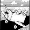
[WIP] Flying Brick
whale2 replied to whale2's topic in LEGO Technic, Mindstorms, Model Team and Scale Modeling
This is kind of final look (excluding the cat). I was moving the wing along the fuselage and now it seems almost in place - the plane is standing still on it's own wheels. Almost loaded with everything - motors, batteries and all structure parts. Weighs 4500 g now. Wires, hoses and electronics will add about 300 more. -
Lego Airbus A300-600R Project
whale2 replied to Chrisf98's topic in LEGO Technic, Mindstorms, Model Team and Scale Modeling
Any pictures? (Except of the real airbus) -
[WIP] Flying Brick
whale2 replied to whale2's topic in LEGO Technic, Mindstorms, Model Team and Scale Modeling
Well, no :( I'm planning to do more on the next week. -
[WIP] Flying Brick
whale2 replied to whale2's topic in LEGO Technic, Mindstorms, Model Team and Scale Modeling
Ha-ha, thanks :) I wishing to have more time for this. -
[WIP] Flying Brick
whale2 replied to whale2's topic in LEGO Technic, Mindstorms, Model Team and Scale Modeling
Some more boring news: stabilizer is fixed to the fuselage. Now after making the elevator and finalizing fuselage walls, wings will be attached for locating CG and moving it to proper place. -
Car Lift
whale2 replied to Sheepo's topic in LEGO Technic, Mindstorms, Model Team and Scale Modeling
Wow! Just like one of the real things I had in my workshop some years ago. Mine (I mean full-scale) used chain for transferring torque to other pillar or two motors and electronic synchronization. I'd suggest cover the axle between pillars as usually cars are quite dirty :) -
[WIP] Flying Brick
whale2 replied to whale2's topic in LEGO Technic, Mindstorms, Model Team and Scale Modeling
Tailplane and fin: -
[WIP] Flying Brick
whale2 replied to whale2's topic in LEGO Technic, Mindstorms, Model Team and Scale Modeling
Maybe it looks like this but in fact it is not. Tail is pretty heavy due to tail fin and stabilizer. Stabilizer alone has 60 cm span. I left small parts of lower fuselage unglued for now to be able to move central section when tail is finished so CG is located exactly where it should. -
[WIP] Flying Brick
whale2 replied to whale2's topic in LEGO Technic, Mindstorms, Model Team and Scale Modeling
It goes, but painfully slow. I've finished both wings and lower central section where wings are connecting to the body and working on the tailplane. Struggling to make it serviceable yet rigid and strong enough. -
[WIP] Flying Brick
whale2 replied to whale2's topic in LEGO Technic, Mindstorms, Model Team and Scale Modeling
In attempt to find CG: Regarding high drag - there should be plenty of thrust - 3 - 3.4 kg at full throttle, if motor/prop specs are right. (Motor test bed soon to come) As it was said, this thing is not expected to be efficient.