

Ptchnk
-
Posts
40 -
Joined
-
Last visited
Content Type
Profiles
Forums
Gallery
Posts posted by Ptchnk
-
-
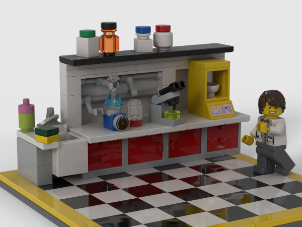
Here is a larger fumehood design

-
15 hours ago, Yoggington said:
This is a beautiful build. I would go so far as to say the best at its piece count in the current BDP. Seeing the inner workings and the planning you had to put in is making it even more appealing.
If you don't make the cut, I'll be happy to purchase instructions.
+1 This MOC is such a nice built and is simply enjoyable to look at. I really like the vibe it's bringing. Add to this the building experience. I would definitely buy this set for me and as a gift.
-
That would be the tap piece (4559a ou 4559b)
And on top of the inner cone pieces, a 1x1 round plate topped by a 1x1 round tile.
I don't think there is any connection between the tube and the inner supports.
-
Here is a chemistry fumehood to complete the Material research lab. The front window can slide up & down for the safety of the minifigs.


-
Thanks for the feedback.
I've made a slightly revised digital version of it.
https://rebrickable.com/mocs/MOC-214640/Ptchnk/farm-tractor/#details
The transition between the front and the cabin in a bit different as well as the back (lights and accessories attachments) and the cabin is 1 plate lower.
I'll update the IRL build if we get the missing part.
-
Wanted to try to build a small farm tractor with available stock parts to go along the harvester (60223) for my kid. Also wanted to have somehow a working front suspension so that the 4 wheels are always on the ground. I used the wheel base 47720 and attached it upside/down on part 2817. Works quite well as front tractor wheel attachment. Kid's happy :)
Here is the results:


-
2 hours ago, SpacePolice89 said:
What do you think about white air tanks for the dark azure and bright green minifigs? The torso already features a lot of white.
Yep the white tank works well for those two...
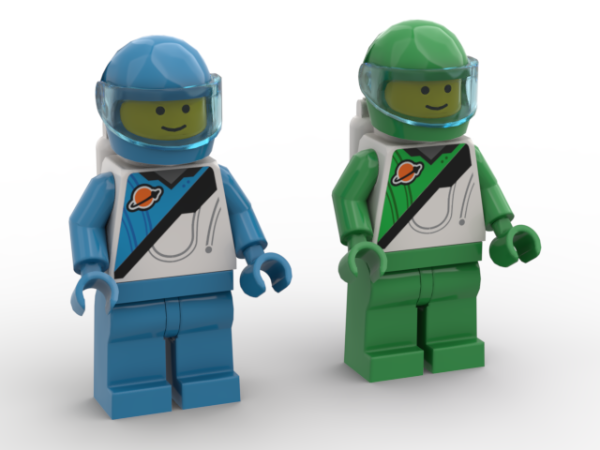
Also like these to include the bright orange torso, this gives a good balance
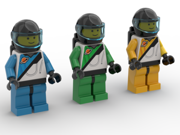
Or these that include all of the new torsos and considering available parts
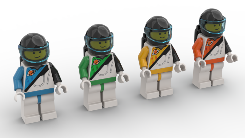
Or these as special units of Space Police ;)

-
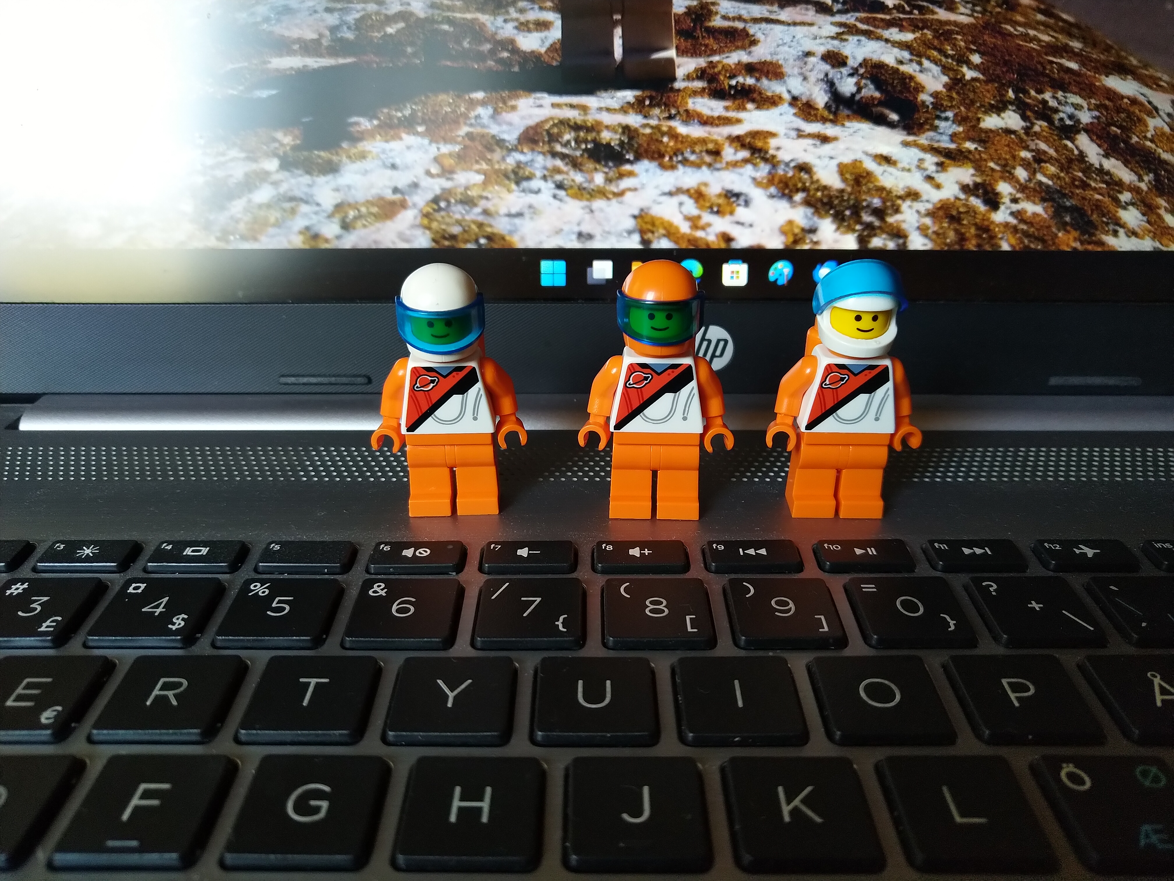
49 minutes ago, SpacePolice89 said:
Yes, those minifigs are very nice. Unfortunately all necessary pieces in the correct colors does not exist for those.
The motorcyle helmet, legs and arms are available in Dark Azure and Bright Green already. Those will just miss the 3838 air tanks but black will work fine with the torso desgin . This already better than for the previous redish orange torso for wich only the arms and hips are available so far.
I'm considering getting those with black hands and blank tank and may keep the black right arm.
-
On 1/24/2025 at 7:28 PM, SpacePolice89 said:
While I prefer the original Futuron style I have no problem with including the new green ones from City or the orange ones from Build a Minifigure in my Space dioramas. The same goes for the Blacktron torso from Space Police III. I make the necessary adjustments so that they'll fit in with my original minifigs and sets.
The is a new set (60446) with 3 new update Futuron inspired torso (bright green, bright light orange and dark azute)
-
On 1/24/2025 at 4:19 PM, Gioppa said:
What i can tell is .. use electric or diesel locomotive, not steam like emeral, becausethe frame is rigid, and when the first wheels enter the inclined, the motorized wheel don't touch the rail and train stop.
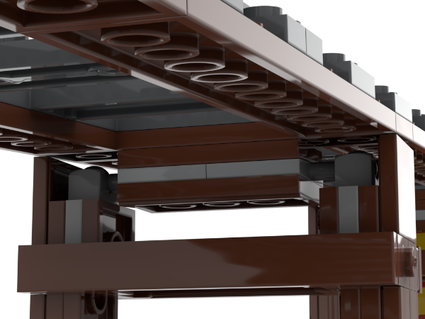
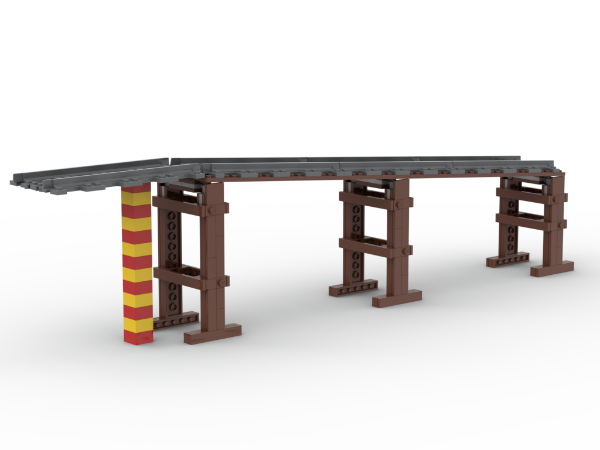
The picture was mainly to share the design of the pillars and the height of the last one (13 bricks).
Of course, the angle for the onset and end of the slope pour have to be lowered to achieve smoother transitions with the flat tracks. The design of the pillar allows a minimum height shift fo 2.5 plates between 2 pillars. Basically a 3 segments section with a total elevation of 5 plates (=2.5 plate per 1.5 tracks) to keep the same spacing between pillar should work. This should correpond to a 1.5+ elevation per track segment which is still quite reasonnable.
On 1/24/2025 at 5:30 PM, zephyr1934 said:Neat idea, and it should lead to some fun physics experiments (don't use your prized $900 MOC, but don't hesitate to use a City train set). I really do mean "fun" though, you and your child can do the engineering to figure out how heavy the locomotive might need to be to get the train up the hill while also exploring the consequences of weight on the down hill side. If they get that, add in a curve right before the upgrade (more drag) or right after the down grade (fun crashes). Back in the 9v era I THINK lego recommended no more than 1 plate rise per 16 stud track segment, but that's where engineering experiments come in, that could be part of the fun with your child- what slope is too much? One suggestion, if the 2 stud step works, it might work even better with a transition of a single segment with a 1 stud climb (so: flat, to one section with 1 stud climb, to many segments with 2 stud climb, then a single section with 1 stud climb then flat again).
My son already started is own crash tests especially down hill. We ended up banking the curve down hill to manage the gain in inerty.
-
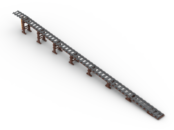
Working on elevated train track with my 7yo for more intricate tracks designs.
Here is a simple design using plates, brackets and ball-join plates.
The highest pillar is about 13 bricks high. The actual setup with a pillar every 1.5 track segment and a reduction of 2 studs (or 5 plates) lead to a slope of about 4.75 degree. I'll see if it works with our trains as i quite like the 24 studs gap between each pillar.Otherwise, a pillar every track segment with a reduction of 1 stud (or 2.5 plates) would lead to a slope of about 3.5 degree.
-
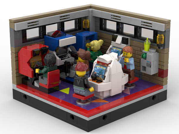
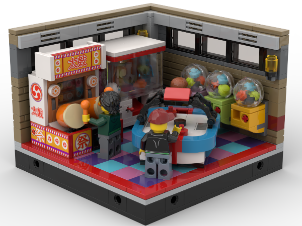
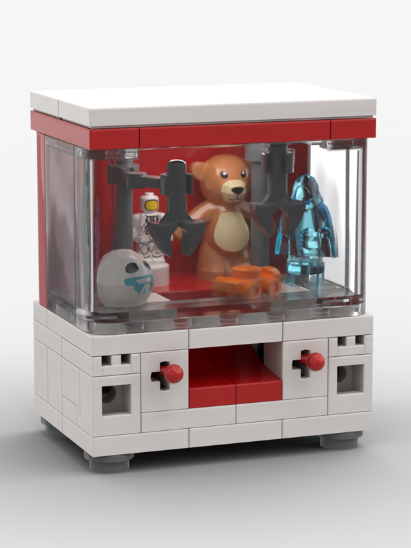
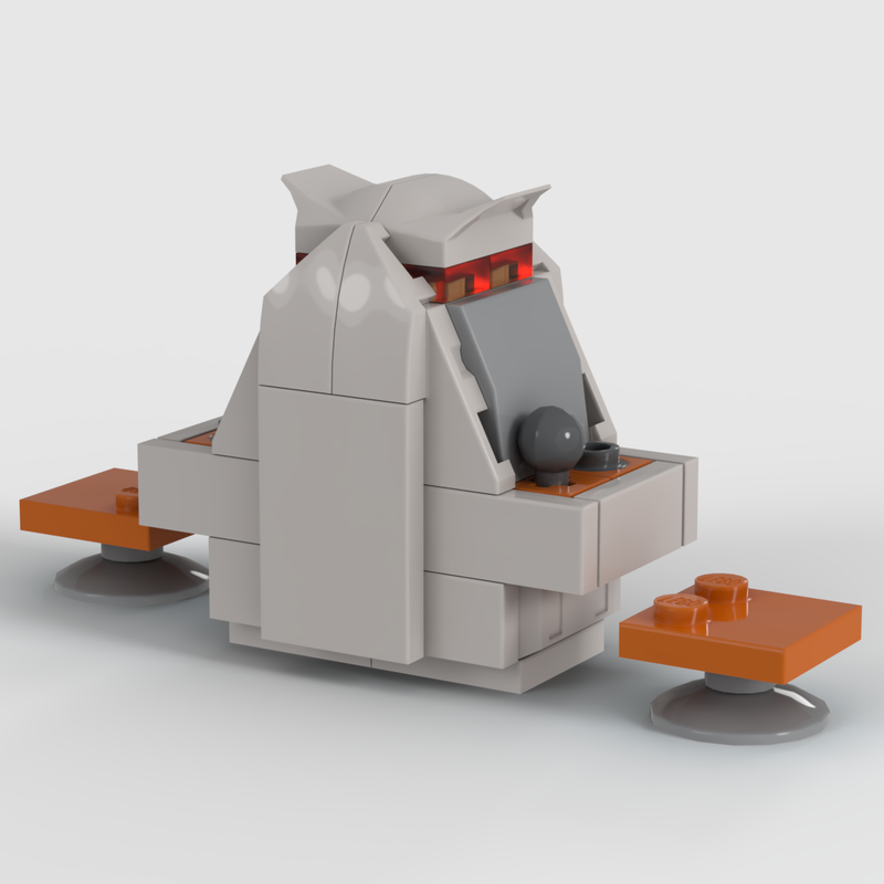
I've made a smaller version of the UFO Catcher so that it is easier to fit it in a building.
First the brick built version:
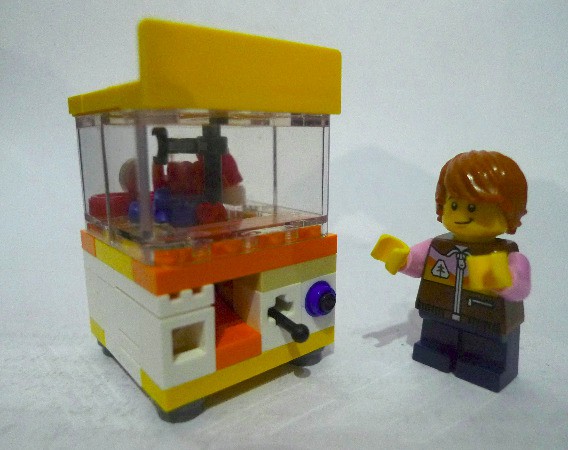
And the digital version for testing the color scheme:

I've also reworked the design of the racing cab from the first post as i didn't like that much the classic seat for this purpose. The build has also been modified to be sturdier as there was some issues with the upper part.


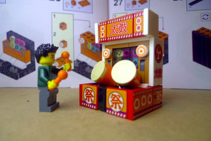
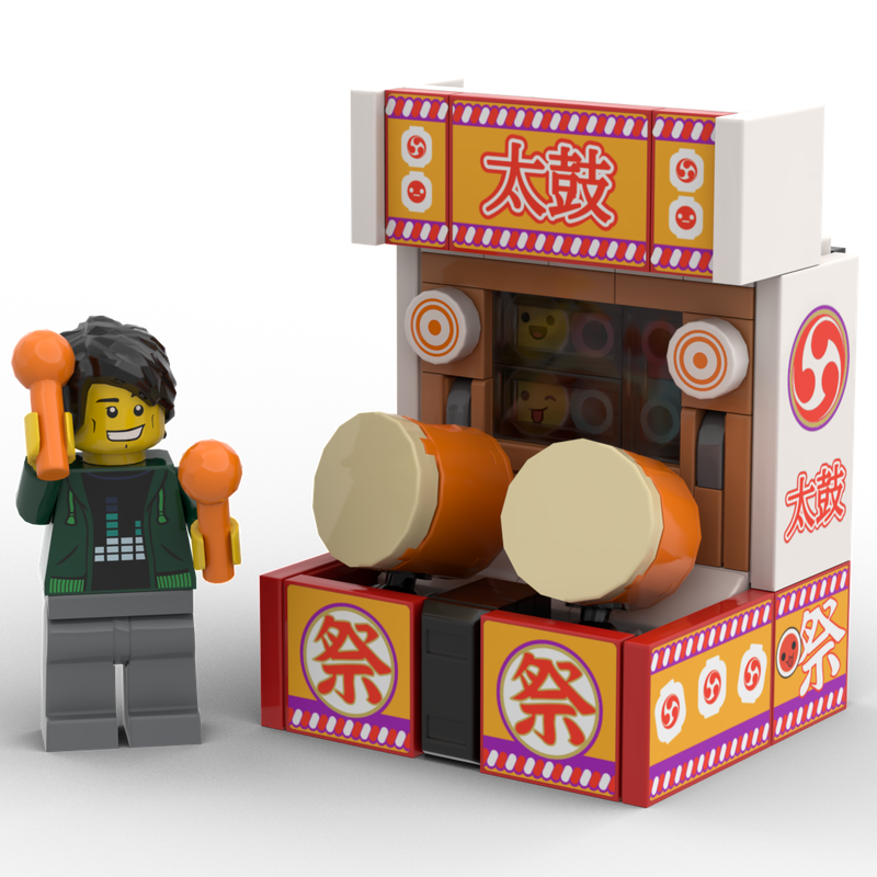
And also here is the brick built version of the Taiko No Tatsujin cabinet

-
Here are a few additions to the Museum paintings exhibition...


-
Here are some small MOCs to explore painting exhibition at the minifig scale.
As it was easier to start with some geometric patterns, here are a couple "Modern Art" painting for your museum or luxious mansion.Feel free to contribute and add desgin to the topic :)


-
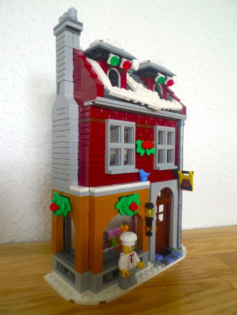
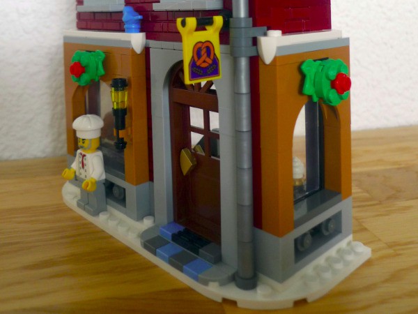
Xmas is coming soon, so here i share the IRL build of the Winter village bakery conversion we did last year to fit the Main Street set we already had.
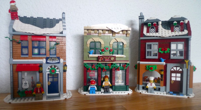
Next to add to the Main Street set would be the Candy Store:


-
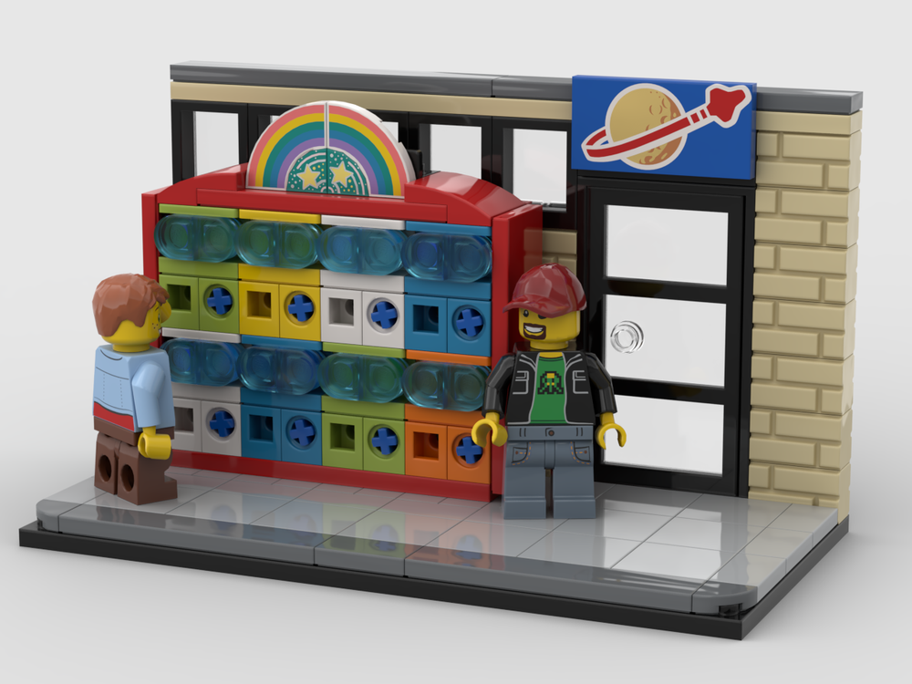
Here a small MOCs focussing on the caspule toys machines to eventually add to your city.
The .io file is here of needed.

-
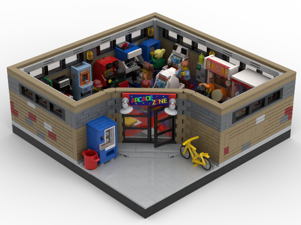
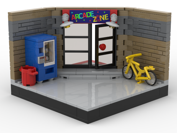
Finally got to do the last corner and the entrance for the 4 Arcade Diorama pieces regrouping different eras and the arcade experience.
The entrance corner probably still need some details to look less empty though.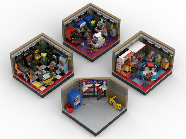
-
On 9/18/2024 at 2:00 PM, Pchan1983 said:
yes, I wonder why they decided to have such a big gap.
Agree, it doesn't look appealing. I'm guessing the gap was needed for clearance issue in the curve on the tracks as the wheels are fixed to the cars (even though there are no curve track in the set). Inter-cars boogies (like the TGV set ones) would have done the trick probably for a cleaner look.
-
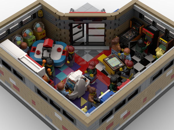
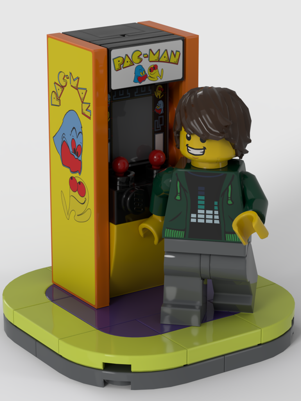
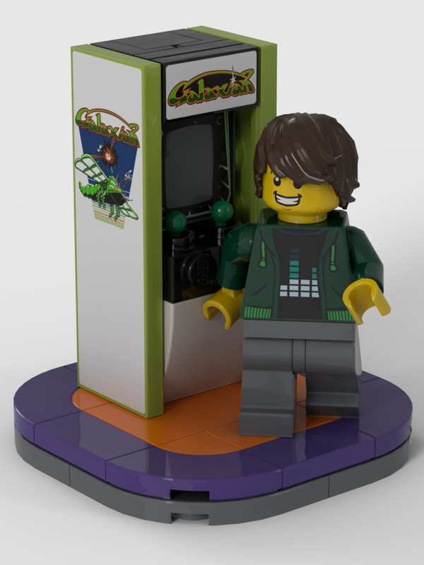
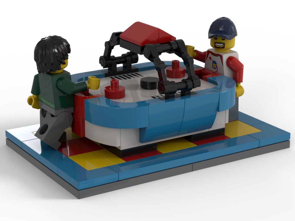
Here the latest addition to the Arcade Series.
A simple and easily customisable (stickers) upright cabinet and a air hockey table
-
Thx a lot for your feedbacks.
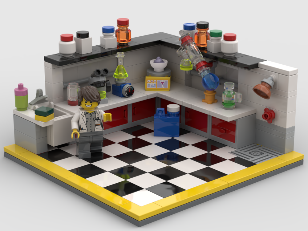
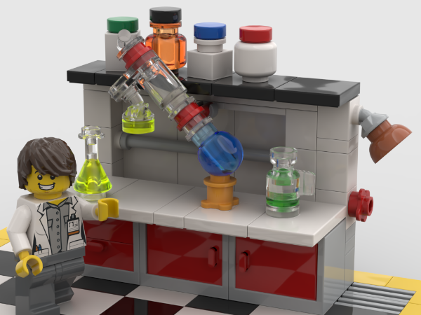
My idea for the larger MOC is to have several dedicated rooms: Chemistry Lab, Furnace Lab, Facilities (X-Ray + ...) , a classroom/meeting room... and of course a coffee break corner.
I've combined both workbenches to start have an idea of the room setup. Stil need to add the fumehood somewhere.
-
I make my own very cheap sitckers with :
- Inkscape software to create the stickers design and the cutting template
- Some A4 paper label (i can probably improve the result here with thinner paper but i have a huge stack to go thru first)
- A good laser printer
- Some crystal tape to prevent wear and bring some shininess
- A laser engraver/cutter (there are fablabs everywhere now)Here is the result

-
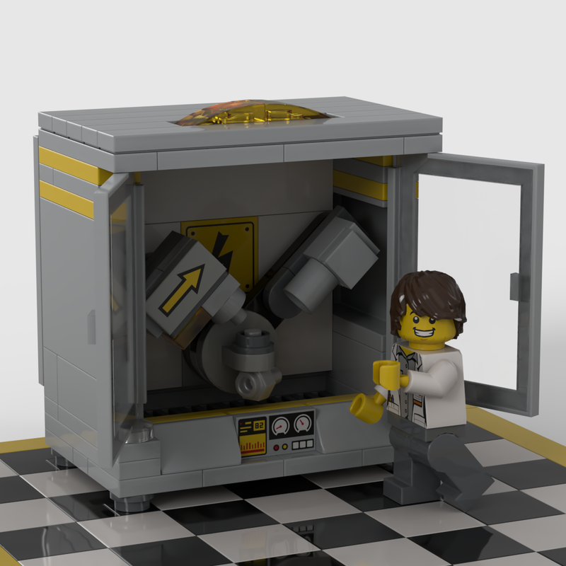
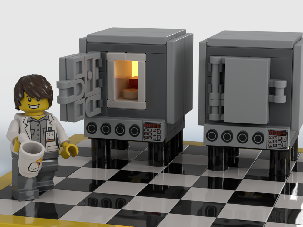
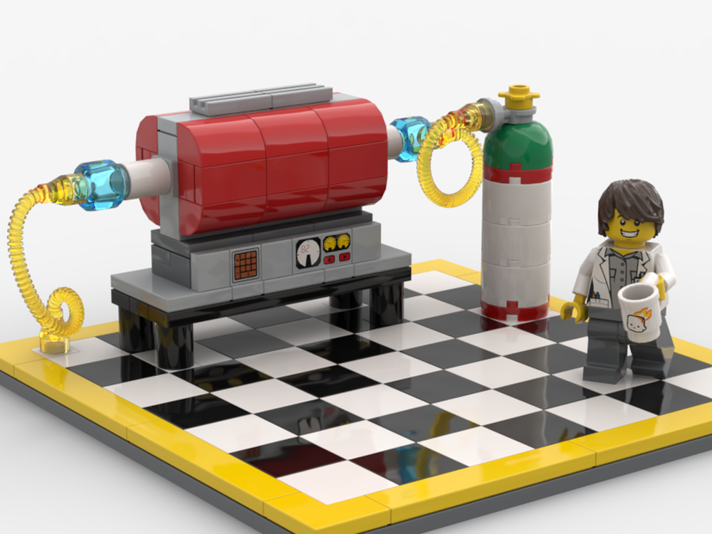
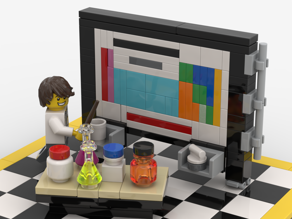
I'm currently working on a series of small MOCs to later be used in a Research Lab larger MOC with several rooms.
So far, i've done an X-Ray diffractometer, a couple high temperature furnaces, a white board with a periodic table and a couple attemps at some lab benches
-
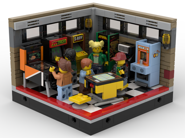
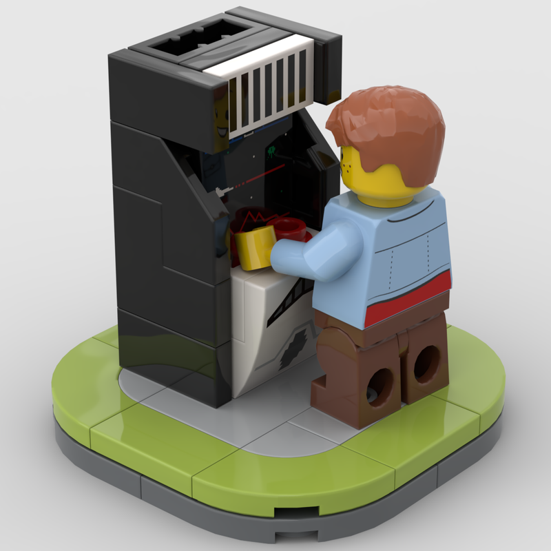
Here a few additions to the arcade series theme
Taiko No Tatsujin - Master of the Drums
UFO Catcher - Claw Machine
Gashapons - Capsule toys machine
Junior Arcade Cabinet
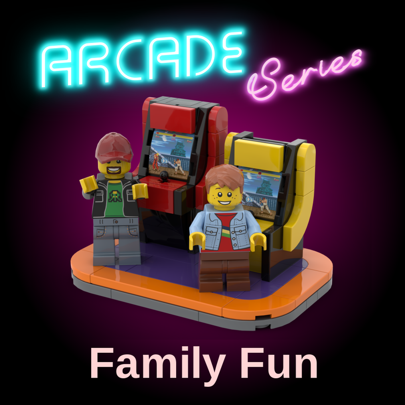
Versus Candy Cab
-
Few modifications to make it more modular. I also want to do an attachment with the entrance


LEGO Sci-Fi Ongoing - Rumors, Speculation, and Discussion
in LEGO Sci-Fi
Posted · Edited by Ptchnk
I like the retro design quite a bit but i also don't like the minifigs choice. Classic spacemen would have been great with it :)
This would go well with my retro space ship :)