
2GodBDGlory
-
Content Count
2084 -
Joined
-
Last visited
Everything posted by 2GodBDGlory
-
42141 McLaren Formula 1™ - Mods and Improvements
2GodBDGlory replied to phmzt's topic in LEGO Technic, Mindstorms, Model Team and Scale Modeling
Glad to hear it! -
42141 McLaren Formula 1™ - Mods and Improvements
2GodBDGlory replied to phmzt's topic in LEGO Technic, Mindstorms, Model Team and Scale Modeling
You know, thanks to the half-stud gaps between cylinders, you could probably get a realistic 120 degree offset on the crankshaft by putting the wedge belt wheels in the spaces between the pistons, and then having 1-2L beams attached to its pinholes. It might not run as smoothly though... -
[MOC] I-Beam Suspension Trophy Truck
2GodBDGlory replied to paave's topic in LEGO Technic, Mindstorms, Model Team and Scale Modeling
Nice job! I love how you went for that very uncommon front suspension design, and I like your solution for the front steering! I put one of these suspensions in a 1:10 Ford F-350 MOC a few months ago, so I can appreciate how hard they can be to design. -
Alternative web model silverchampion 8458 instructions
2GodBDGlory replied to Anubis90's topic in LEGO Technic, Mindstorms, Model Team and Scale Modeling
I just took a look at one of the old instructions websites I used to frequent, and it looks to me like they have the instructions for this Street Sensation--it's a low, street car, right? It doesn't look like this site lets me post links to a specific set of instructions, but if you go here: https://brickfactory.info/, click on the "All Scans: By Number" box, select 8400-8499 from the dropdown list, and scroll down to 8458, you should find them. Would it make sense that this model was built on the same chassis as the main model? Hopefully it was, because the instructions seem to start with the chassis already built. -
42140 - App-controlled Transformation Vehicle
2GodBDGlory replied to Ngoc Nguyen's topic in LEGO Technic, Mindstorms, Model Team and Scale Modeling
Yeah, I'd agree that smoothness is likely more of a motivator then strength. After all, have any of us ever broken a tooth off of a 20T or 12T gear? I haven't, at least, and I tend to use stuff hard. -
42140 - App-controlled Transformation Vehicle
2GodBDGlory replied to Ngoc Nguyen's topic in LEGO Technic, Mindstorms, Model Team and Scale Modeling
So, we do have new gears, but they're much less useful than they could have been... Still, they look cool! I suspect the best use of them will be to get a 1:2 gear ratio in flexible spacings using 12T and 24T gears--sometimes you need a specific ratio like this for something to work, and this should make it more convenient. 20:40 would also get us that ratio, but takes up a lot more space. I suppose it'll also open up some ratios that never really showed up before, like 12:16, but overall, I'd much prefer the 14/18 combo I was hoping for! I guess my old-school 14T gears ain't obsolete yet! -
Technic 2022 Set Discussion
2GodBDGlory replied to Technicallism's topic in LEGO Technic, Mindstorms, Model Team and Scale Modeling
It is an unfortunate color, but it can't just be a standard 12T recolored, because it doesn't have the beveling. Hopefully whatever it is will only be used occasionally, like the 20T clutch gears, leaving the nice black 12T gears being used the majority of the time. -
Technic 2022 Set Discussion
2GodBDGlory replied to Technicallism's topic in LEGO Technic, Mindstorms, Model Team and Scale Modeling
Well, I'm not so sure. Whatever this gear is, it can't be a simple recolor, because it seems to clearly have a circular lip right at the edge, rather than the + shaped ones that current 16T gears have. Based on that, it could be nothing but a new mold for the 16T gear, but I don't think they should be due for that already. As Zerobricks suggested, it could be a 16T variant that can slide on an axle, but from some angles it seriously looks like the gears are different sizes. I did a bunch of counting as well, and I'd agree that there are too many teeth for the near gear to be a 12T, but I think it would work nicely as the 14T gear of the 14T/18T gear combo that I'm really hoping this is. EDIT: Here's an image @R0Sch posted in the 42140 thread: It's got differently colored gears, which would likely indicate prototype parts in one of the pictures, and from this angle, especially the picture to the left, they really look like different sizes. Also, the different shades of blue would make sense to designate two different molds. I guess we won't know anything for certain until reviews come out, but I'm pretty hopeful that there's some new gears here. -
[MOC] Base for a small technic car
2GodBDGlory replied to brick-builds's topic in LEGO Technic, Mindstorms, Model Team and Scale Modeling
Could a Speed Champions body fit over it? -
[TC21] Technic Transforming Vehicle Contest - Results Topic
2GodBDGlory replied to Jim's topic in LEGO Technic, Mindstorms, Model Team and Scale Modeling
Thanks, that means a lot to me! -
[CADA] CADA General Discussion Topic
2GodBDGlory replied to Milan's topic in LEGO Technic, Mindstorms, Model Team and Scale Modeling
Do those of you involved with CADA have any idea if there's any chance of them putting out differently sized clutch gears? Given how often Technic fans demand them, it could be a major selling point for them! -
42141 McLaren Formula 1™ - Mods and Improvements
2GodBDGlory replied to phmzt's topic in LEGO Technic, Mindstorms, Model Team and Scale Modeling
Wow, sounds cool! I do think the tumbler tires look cool, though they may not be the most realistic. It seems like you're going to be closer to a MOC than a mod in the end! -
[TC21] Plymouth SuperBIRD
2GodBDGlory posted a topic in LEGO Technic, Mindstorms, Model Team and Scale Modeling
So, as some of you may have gathered from posts in other topics, I've already been working on my entry for a while. It wasn't that I wanted to start three or four weeks early, but I took a gamble on guessing that the official contest rules would be published soon, and was wrong. Therefore, the first half of my WIP thread is essentially just me talking, without input from others. Also, I expect to finish well before the due date, so please don't feel like I started early in order to gain an advantage that way! Anyways, to date I've taken pictures and written out WIP posts four times. I guess I could stagger posting them to simulate a more normal contest entry, but that seems overly confusing, so I'm just going to rapid-fire my updates here: Update 1: For this contest, the first idea I had that I liked for an entry was a car transforming into an airplane. Not a car transforming into a flying car, but hopefully something more dramatic. The basic idea was that the car would shrink in width to attain the profile of something like a fighter jet, that some sort of rudder/elevator assembly would rise from the trunk, and that the hood and grille would split in half and fold out to create wings, revealing some sort of airplane-style nose underneath. Finally, I hoped to have a propeller fold out of the trunk as well to go on the back. If I could get that all sorted, I would move on to adding as many car/airplane functions as I could fit, such as a piston engine, gearbox, working ailerons, elevators, and rudders, and maybe even flaps and a variable-pitch propellor. I knew that the changing width would cause a lot of problems, so I started by working on the rear suspension and drive. After trying a silly idea with sliding transverse axles, I settled on the design seen here, with two parallel trailing arms for each wheel, with a planetary hub driven with an old female CV joint, as Zerobricks has demonstrated, followed by bevel gears and longitudinal shafts with CV/universal joints at each end, allowing for the axles to slide towards each other freely. I then started working on the actual mechanism to change the width, using two medium linear actuators per end of the car, geared together, and attached to an 11x15 frame that I could build the un-sliding parts of the car off of. Each LA only used four studs of its travel, for a total change in width of eight studs. I then extended the sliding “walls” of the car forwards and started working on the front suspension. Again, I couldn’t do a basic double-wishbone independent suspension design, because of the changing width, so I did a simple sliding-pillar design using the springs from hard shocks mounted on an axle at the steering pivot. I then mocked up a strange steering setup like the one you see here. The Z-shape of the links keeps the hubs parallel to each other regardless of the current width of the car, though the central control axle has to rotate when changing width or the car will automatically steer. At this point, I began thinking more thoroughly about how I was going to transform the front into a plane-esque nose, and realized that I would probably have to design my car to have a pointy nose as well. My plan for the aesthetic had been to simply build something that would work and then try to make it look decent, but I wasn’t happy with the idea of building a nose like this, since it would make the car look very strange. Then inspiration struck, and I decided to forget about designing my own car (which would very likely be very ugly), and instead model a classic Dodge Daytona or Plymouth Superbird, the only real cars I can think of with the nose shape I was after. Another plus was that I could commandeer the massive rear wing on the real cars and use it as a set of dual rudders and elevators, hopefully, which would be easier than having it pop out of the trunk. Also, the fact that the car is very long should help the proportions work out better as an airplane. A final advantage was that I would get to model a good-looking car that is also very boxy—a boon, since my mock-up chassis was already very boxy on the sides. The choice was then between the Daytona and the Superbird, but I chose the latter for three reasons. First, I’ve built two second-gen Dodge Chargers before but no Plymouths at all, and I wanted to do something different, Second, the taillight design on the Plymouth will likely work better with having the propeller fold out, and Third, the name SuperBird is perfect for a car/airplane. With this idea in mind, I printed some blueprints, extended the wheelbase to match, and installed a pair of linear actuators for the front half, connecting them to the rear. Update 2: The next thing I tackled with this MOC was trying to get the basic wing mechanism to work. I wanted the hood of the car to split in half and fold out to the sides, so I found a good pivot point for the wings and messed around with different gearings to get the wings to open the correct amount for the fixed number of rotations required to contract the car’s width. The best gearing for this turned out to be 1:24 worm gearing followed by 8:28 gearing with a small turntable. I also figured out a way to attach the wings from the sides to prevent their motion from interfering with the base of the windshield. I then moved forward, working to finalize the steering at the front. To do so, I added a second Z-shaped linkage to the steering to make the weird linkage sturdier. The linkage is run by a PF M-motor running a worm gear against an 8T gear (The worm is currently removed to make transforming the car during tests easier), which then drives a 12T gear against a 40T gear at the center of the main lever. As mentioned earlier, the change in width will steer the wheels to their maximum and beyond if not counteracted. I considered trying mechanical solutions to isolate these motions, but in the end, I think it will be far simpler and more reliable to mount the motor as I have here and just manually counter-steer as the transformation occurs. The only other change of note is the addition of a micro V8 piston engine under the hood, which will look dwarfed while in car mode, but which is all I can fit while in plane mode. I am now trying to figure out a linkage that will allow me to hook up the rudder(s) that I plan to add at the rear with the steering. Update 3: I’ve now spent a lot of time working out some of the aesthetics on the front. This has meant building the side of the pointy front, which will hinge in and out depending on mode. In car mode, it will be out parallel with the rest of the car, fitting under the hood/wing panels, while in plane mode, it will hinge inwards to create more of an aerodynamic cone shape on the front. I built some of the central aesthetics for plane mode (which will be covered up by the hood/wing when in car mode), evicted the PF M-motor from the front, and got the hinged panel to line up fairly well in both modes. This panel is extremely complicated in shape, though, made up of lots of small pieces. I suspect that it could be made much more elegantly and easily using Technic panels, but the #1/2 and #3/4 panels that would likely be used here don’t exist in LBG, and I am unwilling to buy a lot of parts in some other color to recolor this car. I do have some of these panels custom-painted into LBG, but I’m pretty sure painted parts are not allowed in the contest. I think my shape works well enough, it is just rough to the eye because of the random texture on it. The next step will probably be to mirror these bodywork things and hook up a linkage to work the pulling-in of these panels. Update 4: This update represents a lot of work. I still haven’t worked out the linkage for the pulling-in panels, but I’ve made a lot of progress, nonetheless. The thing I mainly started with was fleshing out the wing/hood panels, but then the advanced weight caused major problems with the wing-deploying system. I should have known that three 8T gears in a row driving the 28T turntable would never take that kind of force without prohibitive backlash, but I was set on using the turntable and this was the only way I could think of. Anyways, I tossed that whole system and rebuilt a much better one using a worm gear to directly drive two 40T gears, to which the wings are attached. It was very hard building this module, since not only the worm shaft, but also the steering shaft and the engine shaft had to traverse this space, one on top of the other. I just managed to get it all to fit, though! Before I trashed the 28T turntable setup, I had realized that I could revive my dreams for working control surfaces on the wings that I had previously given up on by running universal joints right over the center of the turntables. I essentially carried this system over, but decided that since I can only get one shaft out onto the wings, I would have to combine the ailerons and flaps into flaperons. This meant that the bevel gear housing in the middle could not be fixed to anything, since it will have to rotate on its axis to activate the flap function. Unfortunately, I was at my width limit, with no room for support between the bevel gear housing and the U-joint (SaperPL’s 3D-printed U-joint with integrated axles would have been a lifesaver). The best solution I could think of was to mount the bracket on the thin circular holes from minifigure back brackets. I’m not happy with the strength of this setup, so I’ll plan on improving it soon. Other than that, I’ll need to get around to making the linkage for those front panels, reinstall the A-pillar bases, attach the steering motor, and hook up the wing folding mechanism with the linear actuators for compressing the car. (A 32T gear would fit perfectly with just the right ratio. Grrr!) I’m starting to feel like the car has hit the tipping point where it is now too complex to ever work correctly, which happens to me a lot. Hopefully I’ll have the patience to work through the increasingly difficult challenges of packing the rest of the stuff in! -
[TC21] Technic Transforming Vehicle Contest - Results Topic
2GodBDGlory replied to Jim's topic in LEGO Technic, Mindstorms, Model Team and Scale Modeling
Yeah, thanks for putting this contest together! Good job to all the participants; it was a lot of fun! -
[TC21] Plymouth SuperBIRD
2GodBDGlory replied to 2GodBDGlory's topic in LEGO Technic, Mindstorms, Model Team and Scale Modeling
Thanks guys! I was really shocked by how many people voted for my entry once the votes started coming in! -
[MOC] Nissan 240SX
2GodBDGlory replied to BB8's topic in LEGO Technic, Mindstorms, Model Team and Scale Modeling
Yeah, I really like how those headlights turn on when you open them up! The rear view looks really nice too. -
[MOC]/[POC] RC Snowmobile
2GodBDGlory posted a topic in LEGO Technic, Mindstorms, Model Team and Scale Modeling
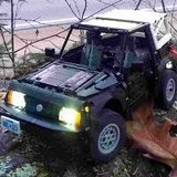
So, this model was thrown together in about two days after inspiration struck! I had been driving my non-Lego RC excavator (A ~$100 USD Top Race one I snagged at a thrift store for $7! All I had to do was throw in my old lithium camera battery to replace the old Ni-Cd one.) out in the snow, and having an awful lot of fun. Anyways, its having tracks and being fun in the snow inspired me to try to build something out of Lego that would be just as fun, and I set on a snowmobile. I don't think these are particularly common to build with Technic, and they're even less common to make RC. I made one a few years back, but it was rather small and weak, and thus no good in the snow. Anyways, I decided to go big and powerful for this one, and am quite pleased with the result! Now, it is a rather quick, crude mock-up, which is why I have the Proof-Of-Concept tag in the title. I really only wanted to build something for fun, which precluded building a body, so normally I wouldn't be posting this, except that it seems to be a rather unique concept. To make it large, I doubled up large tracks and added 9L beams onto them for traction, setting the scale more or less. I drove it using two Buggy motors, directly driving planetary hubs using old female CV joints, which directly drove large sprockets. I originally used medium sprockets, but the large ones got me better speed, as well as more contact with the track. Steering was done with two hard-coupled PF servo motors, since I expected to need a fair bit of torque to steer the skis. The front suspension was a simple double-wishbone setup using two 9.5L hard shocks, but the rear was more complicated, and I had to do some research on the real systems to figure out how it works. Basically, the track support is only attached to the frame by two longitudinal links (11L DBG beams here), a shock absorber, and the track itself. There is a second beam connected to this support, which uses three long shock absorbers to tension the track. It's kind of hard to describe the system, but it basically has normal up/down suspension, plus allows for tilting of the track forwards and backwards as it travels over obstacles. My system could probably have used some work, because the track would often skip over the drive sprockets when the going got tough, but overall it didn't perform too badly! All the electronics were controlled by my new custom 3D-printed 3S lithium battery box. It uses three 18650 lithium cells wired in series and charged while outside of the battery box, to deliver the same theoretical voltage as a Buwizz 3.0, but for way, way, less money. Because of this, I have jokingly inscribed it with the letters PMBW, for Poor Man's BuWizz. Of course, the poor often need to make sacrifices, and in this situation, that mostly means that I have to use external receivers without proportional control. I used two 2.4 GHz Chinese receivers, which ensured a good connection and plenty of current for each buggy motor. Overall, I really enjoyed the project! It was fast and interesting to drive, and also quite interesting to engineer. I'd love to see some other folks take this basic idea further, with higher power, perhaps, a bodywork, and a better tuned suspension! Maybe this is something the Buwizz team would be interested in trying? More images at: https://bricksafe.com/pages/2GodBDGlory/big-snowmobile -
[MOC]/[POC] RC Snowmobile
2GodBDGlory replied to 2GodBDGlory's topic in LEGO Technic, Mindstorms, Model Team and Scale Modeling
Ok, sounds good! -
[MOC]/[POC] RC Snowmobile
2GodBDGlory replied to 2GodBDGlory's topic in LEGO Technic, Mindstorms, Model Team and Scale Modeling
That looks like fun! Will you be testing it in snow soon? -
[MOC]/[POC] RC Snowmobile
2GodBDGlory replied to 2GodBDGlory's topic in LEGO Technic, Mindstorms, Model Team and Scale Modeling
That is cool! It's got quite a similar track/drivetrain design, but is much more polished overall. -
[MOC]/[POC] RC Snowmobile
2GodBDGlory replied to 2GodBDGlory's topic in LEGO Technic, Mindstorms, Model Team and Scale Modeling
Thanks! I'm not sure what the weight is, though, and I already took it apart, so I can't measure. -
[MOC]/[POC] RC Snowmobile
2GodBDGlory replied to 2GodBDGlory's topic in LEGO Technic, Mindstorms, Model Team and Scale Modeling
Yeah, the steering was definitely flawed. Because of the way the motors were attached, I ended up going with a suboptimal attachment of the steering links, allowing for major bump steer. The way the suspension worked in practice, this resulted in some pretty major toe in. It shouldn't be too hard to come up with a better design, though. The ridge could be an interesting idea, and I actually did have a wheel in each ski; I just didn't mention it in the post! Yeah, it probably was front-heavy. It seems like the way the weight is distributed is important for tuning the way the front and rear suspension, and because I didn't build a seat over the rear track, it did end up being heavier up there. I think my custom battery is likely a similar weight to an AA battery box, but I've already taken apart the model, so I can't get you a weight for it. Thanks, I'll look forward to seeing what you come up with! Both of those ideas would be a good thing to try to change to improve performance, as pointed out above. -
Technic 2022 Set Discussion
2GodBDGlory replied to Technicallism's topic in LEGO Technic, Mindstorms, Model Team and Scale Modeling
Yep, it'll probably join the last few years in being a two-pager! -
Technic 2022 Set Discussion
2GodBDGlory replied to Technicallism's topic in LEGO Technic, Mindstorms, Model Team and Scale Modeling
Good point; I'll edit that in! -
Technic 2022 Set Discussion
2GodBDGlory replied to Technicallism's topic in LEGO Technic, Mindstorms, Model Team and Scale Modeling
Yep! Let's count: 1. Friction stud-pin 2. 5x2 panel extension 3. Porsche panel R 4. Porsche panel L 5. 1x1.5 panel extension (Transformation vehicle) 6. Small new gear (Transformation vehicle) 7. Large new gear (Transformation vehicle) 8. McLaren panel R 9. McLaren panel L 10. McLaren frame 11. BMW front shocks 12. BMW rear shocks 13. BMW windshield 14. BMW rims 15. BMW front tire 16. BMW rear tire 17. BMW brake disc 18. BMW front hubs Will we add any more parts to this list in the summer? I hope so!