
technicmath
-
Content Count
29 -
Joined
-
Last visited
Everything posted by technicmath
-
[TIP] A perfect fit
technicmath replied to Didumos69's topic in LEGO Technic, Mindstorms, Model Team and Scale Modeling
Some configurations are indeed essentially duplicates. Some of these were automatically not considered by the java program. Others were retained on purpose to show different setups. -
Regular Polygons with Technic - How many can You build?
technicmath replied to DrJB's topic in LEGO Technic, Mindstorms, Model Team and Scale Modeling
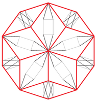
In https://webspace.science.uu.nl/~hooft101/lectures/meccano.pdf by Gerard ’t Hooft the following is stated: "For a multigon of n edges, 10n-27 strips are required, using this method. With a bit more sophistication, I found heptagons made out of 35 pieces, 27 pieces, and any n-gon out of 7n-20 integral strips (assuming n to be odd; if n is even, a slightly different algorithm is needed). A bit of serendipity led to a heptagon of only 15 pieces (see Fig. 9)." "Figure 8: The rigid regular heptagon, using the method of equalizing angles as explained in Section 5. It is built out of 43 integral strips. This algorithm can be extended to any muligon." -
[TIP] A perfect fit
technicmath replied to Didumos69's topic in LEGO Technic, Mindstorms, Model Team and Scale Modeling
Thank you! First, the mathematical formula for such a configuration was derived. Then a java program was written to find solutions where all lengths are natural numbers. These solutions were given to a drawing program. -
New Elementary contest Make a Wishbrick
technicmath posted a topic in LEGO Technic, Mindstorms, Model Team and Scale Modeling
Below are my designs for the contest "Make a Wishbrick" from New Elementary from July-August 2022. The first design is a Plate, Modified 1 x 2 with Pin Holes on Bottom. Its design is a hybrid of the following parts: The second design is a Technic, Liftarm, Modified Perpendicular Holes Bent Thick L-Shape 5 x 7. The enlarged build consists of 3 units. The first unit is only used once in the corner. The second unit is only used twice at the ends. The third unit is used for all other enlarged pinholes. This third unit is positioned in different orientations in order to obtain the perpendicular pinholes. Each of these 3 units is a separate and solid build on its own. These 3 units can be joined together with technic pins. Hence also other configurations of liftarms can be build such as other non-existing parts: Technic, Liftarm, Modified Perpendicular Holes Bent Thick L-Shape 3 x 5 Technic, Liftarm, Modified Perpendicular Holes Bent Thick L-Shape 5 x 5 existing parts: 39794 Technic, Liftarm, Modified Frame Thick 7 x 11 Open Center 71710 Technic, Liftarm, Modified Perpendicular Holes Thick 1 x 15 Each of the 3 units has a dimension of 8 x 8 x 8 studs. These 3 units mainly use the following parts: 35044 Plate, Modified 4 x 4 with 3 x 3 Curved Cutout 80015 Plate, Round Corner 5 x 5 with 4 x 4 Curved Cutout 27507 Tile, Round Corner 4 x 4 Macaroni Wide The enlarged build is built in the same scale as the Plate, Modified 1 x 2 with Pin Holes on Bottom above. The total number of parts in the enlarged build of the Technic, Liftarm, Modified Perpendicular Holes Bent Thick L-Shape 5 x 7 is 986. Congratulations to the winners! -
[TIP] A perfect fit
technicmath replied to Didumos69's topic in LEGO Technic, Mindstorms, Model Team and Scale Modeling
Below are some more examples of a perfect fit: More examples of such configurations can be found at https://bricksafe.com/pages/technicmath/liftarm_geometry_triangle. -
New Elementary contest Make a Wishbrick
technicmath replied to technicmath's topic in LEGO Technic, Mindstorms, Model Team and Scale Modeling
Thank you @gyenesvi, @howitzer and @astyanax! Those parts would indeed be very useful! -
Technic Tessellations
technicmath replied to DrJB's topic in LEGO Technic, Mindstorms, Model Team and Scale Modeling
As previously mentioned by Erik Leppen, the length of some parts is mathematically too long: Below I made another version of this. In fact, this is an example of the Cairo pentagonal tiling: see https://en.wikipedia.org/wiki/Cairo_pentagonal_tiling. Four sides of the pentagon have length 1 and one side of the pentagon has length sqrt(3)-1=0.732... In the example above this is scaled by 4 thus one side of the pentagon has length 4(sqrt(3)-1)=2.928... but the parts used give a length of 3. Below I scaled by 7. Then one side of the pentagon has length 7(sqrt(3)-1)=5.124... thus parts giving a length of 5 will not bend the structure but some space needs to be given. Here are 2 examples: The .ldr file can be found at https://bricksafe.com/files/technicmath/cairo-pentagonal-tiling/Cairo pentagonal tiling.ldr I also made a Penrose tiling: see https://en.wikipedia.org/wiki/Penrose_tiling There are 2 tiles, see below: These use a rectangular triangle with side 2 and hypotenuse 7 thus the third side is 3*sqrt(5) by the Pythagoras theorem. Thus for example in the last tile, the length between the lowest and upper point is 6*sqrt(5)+6 which is 12 times the golden ratio and the length of the red sides is 12. Below is an svg picture: The .ldr file can be found at https://bricksafe.com/files/technicmath/penrose-tilings/Penrose tilings.ldr -
General Part Discussion
technicmath replied to Polo-Freak's topic in LEGO Technic, Mindstorms, Model Team and Scale Modeling
There is a strange difference for the part Technic, Liftarm, Modified L-Shape Quarter Ellipse Thick 2 x 5 (80286). The shape between the 2 last pin holes is different: see the images below. The image on BrickLink is this: This is the same as the image on Bricks and Pieces which is this: But the image from ldraw is this: This is the same as the image from the review of 42137 from @Jim which is this: Is the shape from the images on BrickLink and Bricks and Pieces a pre-production shape? -
[WIP] Aston Martin Valkyrie
technicmath replied to Jeroen Ottens's topic in LEGO Technic, Mindstorms, Model Team and Scale Modeling
Another possible solution for the rear lights is this: The .ldr file can be found in the same folder: https://bricksafe.com/files/technicmath/aston-martin-valkyrie-rear-lights/Rear lights_B.ldr -
[WIP] Aston Martin Valkyrie
technicmath replied to Jeroen Ottens's topic in LEGO Technic, Mindstorms, Model Team and Scale Modeling
@Jeroen Ottens A possible solution for the rear lights is this: The .ldr file can be found in the same folder: https://bricksafe.com/files/technicmath/aston-martin-valkyrie-rear-lights/Rear lights.ldr -
[VIDEO REVIEW] 42131 CAT D11T Bulldozer + Control+ profile test
technicmath replied to kbalage's topic in LEGO Technic, Mindstorms, Model Team and Scale Modeling
Thank you @kbalage for this review! At 4:32, you mention "It is not highlighted in the manual but make sure to pay attention to the position of these gears: if you add one of them the other way around, the linear actuators will work in the opposite direction.". I think that the actuators will turn in the same direction, independent of the positioning of the 20 tooth idler gears. However, at that place in this set, the same mistake is made as in set 42082, which is demonstrated in this video from @Jim: This mistake was already made in set 8043 from 2010! See this post from @Blakbird -
42131 - CAT D11 Bulldozer
technicmath replied to Maaboo the Witch's topic in LEGO Technic, Mindstorms, Model Team and Scale Modeling
Is this a new liftarm with alternating pin holes? This part is new in yellow: -
This is a front live axle with kingpin inclination with angle atan(1/4)=14.036... degrees diff lock portal axles with 8/24 gear reduction constant velocity joints Ackermann steering The following picture shows the very high ground clearance and highlighted kingpin axis (in red): A .ldr file can be found on bricksafe. This .ldr file includes building steps. There are 2 black steering links on top and 2 grey links at the bottom. These create a 4-bar linkage. A caster angle can be obtained by angling the whole axle by setting up the 4-bar linkage properly.
-
Future Set Wishes and Speculation
technicmath replied to SheepEater's topic in LEGO Technic, Mindstorms, Model Team and Scale Modeling
I made a realistic gearbox here: This gearbox has 4 gears, has a realistic setup, can handle very high torque, fits in the studless grid construction and runs with very low friction. It would be even better if Lego made a 24 tooth clutch gear, which is in my opinion actually more useful than the 20 tooth clutch gear. -
Front live axle with kingpin inclination, diff lock, portal axles, constant velocity joints, Ackermann steering
technicmath replied to technicmath's topic in LEGO Technic, Mindstorms, Model Team and Scale Modeling
Thank you! Yes, indeed, the bar at the front controls the steering, there is indeed no rack and pinion. The steering arm has two of this part at the ends:. This steering arm is moved by moving the black arm with the 1 x 9 liftarm on top. This black arm moves together with the suspension and is controlled directly from the chassis of the vehicle. Thank you! The .ldr file contains building steps. At some points, the order of these building steps needs to be followed precisely because some parts can only be placed before other parts. Also, in some building steps, multiple parts are inserted in the same step. In this case, it is sometimes necessary to build some of these parts together before mounting it to the main build. I also made a corresponding rear axle with a diff lock, portal axles and the same width as the front axle: The following picture shows the very high ground clearance: A .ldr file can be found on bricksafe. This .ldr file includes building steps. The links: Front axle: https://bricksafe.com/files/technicmath/front-live-axle-with-kingpin-inclination-diff-lock-portal-axles-constant-velocity-joints-ackermann-steering/axle.ldr Rear axle: https://bricksafe.com/files/technicmath/front-live-axle-with-kingpin-inclination-diff-lock-portal-axles-constant-velocity-joints-ackermann-steering/axle_rear.ldr -
Front live axle with kingpin inclination, diff lock, portal axles, constant velocity joints, Ackermann steering
technicmath replied to technicmath's topic in LEGO Technic, Mindstorms, Model Team and Scale Modeling
Thank you! Yes, I have built it in real bricks (except for some parts such as the differential which I don't own) and the construction is very strong. Simplified in which way? For example, the design can be enormously simplified by omitting the kingpin inclination and diff lock and then also the part count will be much lower. But these are the main features of the design. -
Technic 2021 Set Discussion
technicmath replied to LvdH's topic in LEGO Technic, Mindstorms, Model Team and Scale Modeling
In set 42128, there seems to be this part in blue. This came so far only in 3 sets: https://www.bricklink.com/catalogItemIn.asp?P=32065&colorID=7&in=A and last time in 2003. There also seems to be a 11L version of this part: This can be seen at the back below the orange 3 x 11 panels and also at the back fork. -
[WIP] Ford Sierra RS500
technicmath replied to nicjasno's topic in LEGO Technic, Mindstorms, Model Team and Scale Modeling
@nicjasno In the previous designs, there is an even number of gears in the geartrain. Thus the first and last gears turn in opposite directions. If you want them to turn in the same direction, an odd number of gears can be used. For example as follows with gears 12-24-20-12-24 (from bottom to top): Design A: Design B: At first sight, the gears in design A and B are on the same coordinates, but they are not because the hole of the 1 x 1 Technic Brick is 0.015 stud higher than the standard studded grid. Thus the distances from top to bottom are: Diagonally between the 24 and 12 tooth gears: in design A it is sqrt(2^2+1^2)=2.236..., in design B it is sqrt(2^2+1.015^2)=2.242... and the optimal theoretical distance is (12+24)/16=2.25. -> Design B is better Vertically between the 12 and 20 tooth gears: in both design A and B, the distance is 2, which also is the optimal theoretical distance (12+20)/16=2. Vertically between the 20 and 24 tooth gears: in design A it is 2.785, in design B it is 2.77 and the optimal theoretical distance is (20+24)/16=2.75. -> Design B is better Vertically between the 24 and 12 tooth gears: in both design A and B, the distance is 2.2+0.015=2.215 and the optimal theoretical distance is (12+24)/16=2.25. -
[WIP] Ford Sierra RS500
technicmath replied to nicjasno's topic in LEGO Technic, Mindstorms, Model Team and Scale Modeling
@nicjasno The above gear combination can be made as follows. The orange 20 tooth gear needs to be replaced by a 28 tooth gear. Edit: an even better solution is this one: At first sight, the gears are on the same coordinates as in the previous solution, but they are not because the hole of the 1 x 1 Technic Brick is 0.015 stud higher than the standard studded grid. Thus now the distances from top to bottom are: Diagonally between the 24 and 28 tooth gears: the distance in real life is sqrt(2.515^2+2^2)=3.213... and the optimal theoretical distance is (24+28)/16=3.25. Vertically between the 28 and 24 tooth gears: the distance in real life is 3.3-(2*0.015)=3.27 and the optimal theoretical distance is (24+28)/16=3.25. Vertically between the 24 and 12 tooth gears: the distance in real life is 2.2+0.015=2.215 and the optimal theoretical distance is (12+24)/16=2.25. @tomek9210 The chain does not fit with the 12 tooth gear. -
[WIP] Ford Sierra RS500
technicmath replied to nicjasno's topic in LEGO Technic, Mindstorms, Model Team and Scale Modeling
@nicjasno In your stream "Lego Ford Sierra Live Stream 54 - Is this the turbo?" (see below), there is a gear combination situated at the engine with the gears 12 (at the bottom) - 24 (at the side) - 16 - 16 - 16 - 24 (two times at the top). This can be made with less gears with these options: 24 24 20 12 20 12 For the gear combination between 24 and 20, the distance is 2 both horizontal and vertical. This is not a very good solution since then the diagonal is sqrt(2^2+2^2)=2.828... Multiplying with 16 to obtain the number of teeth on the gears gives 45.254... but 20+24=44 and this gap between 45.254... and 44 is too big. A better option is this: 24 24 28 24 12 For the gear combination between 24 and 28, the horizontal distance is 2 and the vertical distance is 2.5. Then the diagonal is sqrt(2^2+2.5^2)=3.201... Multiplying with 16 to obtain the number of teeth on the gears gives 51.224... And 24+28=52 which should be close enough. -
AMA with Element Designers (Ask me Anything)
technicmath replied to Jim's topic in LEGO Technic, Mindstorms, Model Team and Scale Modeling
Why is the axle from this part 3 studs long while the axle from this part is 2 studs long? I do not complain, I find it very useful that the axle is 3 studs long because then it is easier to build a strong drivetrain with liftarm-gear-liftarm which requires a length of 3 studs on the axle. Why can an axle slide in this part but not in this part ? That is a necessary property for some applications such as in a multilink suspension. (Of course there are other solutions to make a sliding axle but these require more space.) Why is this part 3 studs long? At first sight it seems that it could be 2 studs long which would make constructions more compact, but maybe then the connection with this part would be less strong and/or the angle they can make would be less? -
Gears-efficient gearbox
technicmath replied to technicmath's topic in LEGO Technic, Mindstorms, Model Team and Scale Modeling
Below is a possible solution to make this gearbox in a studless construction: The orange 36-tooth gears need to be replaced by 28-tooth gears and the dark bluish gray driving ring should be the newer 3L version. The 24-tooth gear at the bottom and at the right, the 12-tooth gear at the bottom and the 20-tooth gear at the right provide possibilities to go back in the studless grid. Or universal joints can be used to go from the axle through the 1 x 1 technic bricks back to the studless grid. -
Gears-efficient gearbox
technicmath posted a topic in LEGO Technic, Mindstorms, Model Team and Scale Modeling
The idea of @nicjasno in for a gearbox can be improved as follows. There is no need for a 24 or 28 gear with clutch: the setup can be built as (two axles) 28-24-(20 with clutch)-clutch-(16 with clutch) (16 with clutch)-clutch-(20 with clutch)-24-28. For these gear combinations, a distance of 44/16=2.75 studs is desired. By using the above configuration, there is a distance of sqrt(2^2+2^2) or approximately 2.828 studs. This can be improved by xx -> 1 x 2 technic brick with 2 holes with axle at the left xxxx -> 1 x 4 technic brick with axle at the right. Then the distance is sqrt((3*2/5)^2+2.5^2) or approximately 2.773 studs, which is much closer to the desired 2.75 studs and then the gears run much smoother. -
[MOC] 1968 Dodge Charger
technicmath replied to nicjasno's topic in LEGO Technic, Mindstorms, Model Team and Scale Modeling
Sorry, I did not realize that a flex axle should go through that place. Another possibility is to use this piece: The axle hole of this piece connects to the black liftarm. Then a 3L liftarm (possible at both sides of the above piece) can be used: 2 pin holes in the pins of the above piece and 1 pin hole at the top where the flex axle can go through. -
[MOC] 1968 Dodge Charger
technicmath replied to nicjasno's topic in LEGO Technic, Mindstorms, Model Team and Scale Modeling
@nicjasno In at 2:03:00, you try to place this piece: You can also achieve this by using this piece: supported from below by this piece: Also, above the front wheels, there is a diagonally placed 13L liftarm. This makes a triangle with sides 5, 11 and 12 but that is not a rectangular triangle. To make it a rectangular triangle, it should change to 5, 12 and 13. For example by using one of these two constructions: Change the mounting point at the back of the wheel 1 stud to the inside and 1 stud to the back. Then it can attach directly below a pin hole of the 5 x 7 frame. The mounting point in the front will then go 1 stud to the inside, nicely on top of the 5 x 7 frame. This solution might interfere with the grey 2 x 4 liftarms. Change the mounting point at the front 1 stud more to the front. The car is a fantastic project. Thank you for the streams!