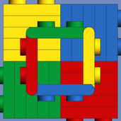
SNIPE Posted January 6, 2014 (edited) Hi I am working on gear pairs meshed directly together, in a 2 by 2 arrangement. Two gears on each of the two axles - However one gear is an idler gear which is driven by the other gears instead of with the same rotation speed as the motor. However I'm not sure if the ratio for the idler gear will be 1:1 since there is two 16 tooth gear gears in either example I don't think it is 1:1 though it should be what the other two gears are, so say 3:1 or 1.6:1 but I'm unsure as it's hard to tell. The yellow axle joiner goes to the motor, I'm using a differential to replicate a single 24 tooth idler in the first image. Obviously the dark grey gears are the idlers. Any ideas what it could be. More gears can be used with studed beams and plates such as 16 tooth +12 tooth or 20 + 20 or 16 + 20 etc. Regards, S Edited January 7, 2014 by SNIPE Share this post Link to post Share on other sites
DrJB Posted January 6, 2014 (edited) Can't you just cut the differential? You'll get 2 idlers then. In the first picture, the ratio (between input shaft and differential) is 8/24=1/3 In the secnd pitcture, the ratio is 10/20=1/2 Both above are calculated between the driv-shaft (from motor) and idler gear (differential in 1st pic) If however you want the ratios between the input shaft, and what appears to be the output (2nd) shaft, then those numbers are: 1/1 and 10/20=1/2 Does this answer your questions or there is more? Edited January 6, 2014 by DrJB Share this post Link to post Share on other sites
SNIPE Posted January 6, 2014 No, the other half of the diff is not used at all there is two images for two examples each uses 1 idler gear. Share this post Link to post Share on other sites
DrJB Posted January 6, 2014 Right, I only suggested to 'cut' the differential to have a more 'compact' construction. Share this post Link to post Share on other sites
SNIPE Posted January 6, 2014 (edited) I actually use a 12 tooth clutch gear with the spring plates removed, makes a good 24 tooth idler however this would add more confusion and it was catching on the liftarm Edited January 6, 2014 by SNIPE Share this post Link to post Share on other sites
arik Posted January 7, 2014 As the idler gear doesn't rotate any axle, I'm not sure it makes sense to calculate gear ratio for it. You would drive yet another gear with the idler, so that would define the gear ratio. If you'd drive a 8 tooth gear with the 24t idler (driven by 8t and 2x 16t), it'd be 1:1 ratio. Driving a 24t would make it 3:1, right? As far as I understand, the idler gears do not contribute to the gear ratio (only direction possibly). Share this post Link to post Share on other sites
SNIPE Posted January 7, 2014 (edited) Idler gears can change the rotation and speed aswell as mechanical advantage if you add different sizes so they do have a ratio but if its say 1.1 it has little effect other than friction and their weight. The idler gear is the output in both of my examples. Edited January 7, 2014 by SNIPE Share this post Link to post Share on other sites
Technyk32231 Posted January 7, 2014 Idler gears don't have any effect on the final gear ratio, unless there are 2 gears on one shaft. Example: An 8t, 24t, and 40t gear meshed inline. 8:24 = 1:3. 24:40 = 3:5. 1:3 x 3:5 = 1:5. Or... 8:40 = 1:5. Share this post Link to post Share on other sites
SNIPE Posted January 7, 2014 (edited) So for the second image the ratio is 1.6:1 right? Or 1.6:1-1:1 if you wanna include the ratios that are the same The idler doesn't have to be the same as the gear under it such as in the first image, that should be 1:1-1:3 Take a look at the below diagram then picture the yellow gear as an idler, now you can have one axle along the top instead having it split, this means less space used up as there's only two axles that need supporting and the gears can be right up against each other as pairs. http://www.cdxetextb...poundgears.html Edited January 7, 2014 by SNIPE Share this post Link to post Share on other sites
DrJB Posted January 7, 2014 Idler gears don't have any effect on the final gear ratio, unless there are 2 gears on one shaft. Example: An 8t, 24t, and 40t gear meshed inline. 8:24 = 1:3. 24:40 = 3:5. 1:3 x 3:5 = 1:5. Or... 8:40 = 1:5. You are right. But let him get to that conclusion based on what he'll mesh to the idlers. If you have compound gearing, then the overall transmission ratio (TR) is TR= (Z1/Z2) × Z3/Z4) In the specific case where an idler is used, Z2=Z3 and the idler essentially drops out of the equation, and its number of teeth do not matter. Let us see first what the rest of the construction looks like, and we can debate then. Share this post Link to post Share on other sites
SNIPE Posted January 7, 2014 If I add a gear to the idler and one to the 12 tooth gear their ratios should be different even if its the same gear being added. Share this post Link to post Share on other sites
arik Posted January 7, 2014 Yes, but regardless of the idler gear. You get the same ratio whether you connect with the idler or the gear driving the idler. Nice design nevertheless. Share this post Link to post Share on other sites
SNIPE Posted January 8, 2014 (edited) I see now, yea, shame lego don't make other size idlers with clutch teeth as I'm stuck with the 18 tooth idler. Edited January 8, 2014 by SNIPE Share this post Link to post Share on other sites
trekman Posted January 8, 2014 I cut one of my 24-16 differentials into a 24T clutch gear. It is a great job and was needed for one particular application. Surely it is only a matter of time before TLG gives someone a Stanley knife in the factory and tells them to make a few? Share this post Link to post Share on other sites