John Hill Posted September 17, 2013 I have fitted a few of my LEGO trains with DCC and have a commercially made DCC controller. Unfortunately the controller is very difficult to operate and although I could no doubt buy a better one I have chosen to experiment with writing software and using a PC. I have chosen not to use anything like an Arduino but instead am trying to create the DCC signals direct from a PC under Winderz, in the past this would have been easy but since the operating system has put increasing separation between the user and the real world it has become more of a challenge especially as PC parallel ports now seem to be a thing of the past. The route I have chosen is to have my software write ".wav" sound files containing the DCC signal forms. The only complication encountered so far is that the sound device must be programmed for a non-standard sample rate and not all sample rates work however 17250 samples per second does, at least with my sound device. The only 'electronics' required is an LM339 chip as a comparator and an LMD18200 H-bridge motor driver IC. I am using a PC power supply for 12V for the track and 5V for the ICs. Results so far have been promising but not totally satisfactory with the train occasionally pausing or putting on a burst of speed. I presume there are caused by the DCC decoder getting corrupted packets although it is difficult to see how this could be happening with each packet having a check byte. I would like to check the wave form but my analogue scope is only partly useful and I would be grateful for any suggestions on how to do this. Thanks. I have just merged your two topics about DCC. In principal the same topic. (JK) Share this post Link to post Share on other sites
spzero Posted September 17, 2013 sounds like a great idea, am i reading right that you are going to miss out the controller and wire the pc straight to track, that would be ace, would mean a much cheaper alternative to buying a dedicated controller, just get some software, It might be worth talking to some train guys on a model train forum as most on here don't use DCC, I have used it in the past and loved i but its not synonymous with LEGO. Keep us posted though Share this post Link to post Share on other sites
John Hill Posted September 17, 2013 I have a number of 9V trains I have converted for DCC by installing the decoder chip in the motor housing but as we all know this is rather difficult to do in a 12V motor so I have an alternative. For 12V DCC I install the decoder chip outside the motor, two wires to the motor sockets and two wires to copper brush pickups that contact on the metal 9V rails. The 12V pickups I just hold in the fully up position with tape. This system works well except that the copper brush pickups are not the best idea and I hope to make metal bogey wheels to improve the contact. The copper brushes are tufts of copper braid taken from old computer cables and held near the wheels of a bogey with hot glue which sticks well to LEGO and can be easily peeled away when required. Some people tell me that I will "fry my 9V motors" by running them on 12V DCC but I dont believe them and so far I have not had a single 9V motor failure. My theory is that as the 9V motors are being fed PWM there will be no stress on the motor unless attempts are made to drive them at faster or heavier loads than they would have been able to handle on 9V DCC. This is fortunate because I can mix 12V motors and 9V motors on the same track, the 12V trains may be down on power a bit and I expect I could increase the DCC volts a bit (15V maybe) without stressing anything. I hope you find this interesting and maybe useful. Share this post Link to post Share on other sites
John Hill Posted September 17, 2013 Obviously I cant drive the tracks directly from the output of the sound card but my software does cause the sound card to output DCC format signals and it is just a matter of using the motor driver chip to up the power enough to drive the tracks, the other IC just trues up the shape of the signals that are distorted by the audio output circuit. All the controller software is in the PC, my software looks really crude but I hope it will prove easy to use. Right now I can put about a dozen 'trains' on the screen each one with a throttle, brake, reverse button that can be operated by a finger on the touch screen. If it works well I might develop that "human interface" a bit more! I have talked to a few train guys but I never struck the right person! Of course just mentioning that I was using this for LEGO brought fourth a whole horde of folks with ideas totally at odds with mine! If I can get this to work I will certainly be going back to those boards as some guys did express genuine interest. Share this post Link to post Share on other sites
Heppeng Posted September 17, 2013 (edited) It is! I doubt at this stage that I will be going DCC, but I am adapting 9V power functions motors to pick up from 12V track by adding somewhat crude but effective brass strips as pickups under the bogies, and soldered on to half of a PF extension lead so the motor itself is not in fact altered. As part of the process I checked the operating voltages - For a 12V motor, derailment speed on corners with a light train = 10V. Same speed on a 9V PF motor requires 7V. So all that happens is I don't use so much throttle on 9V motors which means that in normal circumstances they will not see anywhere near 12V. I expect that you can set the CV values on each chip to fine tune them to each type of motor so that they all respond in the same way, i.e. step 4 on a 12V motor gives the same speed as step 4 on a 9V motor Edited September 17, 2013 by Heppeng Share this post Link to post Share on other sites
JopieK Posted September 17, 2013 I have done experiments and did not like the way that it affected the performance of my 9V motors. Apart from that, DCC is a nice but expensive way to run trains. Together with my high school students we are developing a universal system that uses Arduino / PF / Xbee / BLE to run trains and peripherals. Share this post Link to post Share on other sites
Bricktrix Posted September 17, 2013 JopieK, I can only suggest that you have not set the cv values well enough if your getting poor performance from the 9v motors. It can take weeks if not months of trial and error to adjust them all, but it is possible to get them to perform 100% better than using standard 9v DC control. John Hill, I'm totally confused as to what your doing? You mention 12v and 9v motors, running off 9v track? From what I can work out, your trying to write your own software for a controller before you know the converted motors are operating perfectly on a DCC system / controller? If I am correct then your running before crawling and I would say now to stop with your train of thought. You will fry your 9v motors if your putting unregulated 12vDCC directly through them. PWM means that the max power is getting straight to the motor, even using speed setting 1, it needs to be regulated with the amps ( or the other way around, I always get them mixed up but my friends do not!) You certainly need to know that your motors are working perfectly via a DCC controller before attempting to write your own code for a controller! DCC conversion into the LEGO 9v track system is possible and if done correctly works extremely well, however it takes a LOT of time, trial and error to get right. It can be done completely safely, there are cv settings for voltage input, amps input, which protect the LEGO motor. I use an NCE Powercab controller with booster, which is putting 14v through the track, but the cv settings have been set for the chip so the motor doesnt draw anymore than 9v. The chip draws more, but we then limit the settings for sounds, lights, etc to all draw safe amps / volts for them. The motor control parameters can take weeks of setting up. The LEGO motors need to be set to a non flywheel setting, on a Loksound V4 its usually the opposite end of the factory setting. The speed curves need to be fine tuned, parameter K in cv 54 try reducing + cv52 for fine tuning. cv55 try increasing, along with cv51 for fine tuning. The back emf cv53 needs adjusting also. All these are best experimented with by adjust a value of 5 each time and test the results. The "cat out of hell" setting also has some bearing (or appears to have done with mine). You need to set the index register correctly (cant remember if its 0 or 1, read the manuals) then set cv 54 to 0 and press f1. This zooms the motor off at full speed for a few seconds and automatically adjusts all the settings, however, these settings are nearly always the opposite of what they need to be! Yup, makes no sense, but after having done that with mine, then going back and fine tuning all the speed curve and load settings, I now have 9v motors opperated through 12v DCC that can pull a full weight train without surge or stutter at speed step 1 all the way through to speed step 28. The motors will "whine" a little on speed steps 1-3 as so much load is on them...the whine means its not doing the motor much good, but again you can control how long they are on those speed steps for. I have a couple of topics using DCC conversions: http://www.eurobricks.com/forum/index.php?showtopic=86867 http://www.eurobricks.com/forum/index.php?showtopic=84421 Share this post Link to post Share on other sites
John Hill Posted September 18, 2013 Bricktrix, it is quite simple really. 9V and 12V LEGO trains fitted with DCC decoder chips (internal for the 9V and external for the 12V) run perfectly well with my Digitrax Zephyr controller but the controller is very awkward to use having only one throttle and requiring multiple button presses to select the train to be controlled (just one example of why I find this controller unsatisfactory). I can run my 12V DCC trains on the 9V tracks when I fit them with pickup brushes. I can mix 9V and 12V on the same track safely as I never ask the 9V motors to do more work than they were designed for. I certainly do not run any motors on "unregulated 12VDCC" whatever that may be, as my motors are all fed from the PWM output of the decoder chip. Thank you for the comments regarding setting up the decoder tables but really they are not at issue as the motors run perfectly well, 9V and 12V, on my Digitrax controller. I use the most simple Digitrax decoders available at the time and even N gauge decoders appear adequate for LEGO motors. The software for a minimal controller is really quite simple as the basic control packet is only a few bytes, the difficult part is frequency shift modulating the track supply with this data and that is what I am doing with the PC sound output. The only problem I have at this point is confirming the waveform that is being put on the track, it appears to be right as the decoders do respond to commands but at times they go off and do something else, for example pause, slow, speed up. Considering the robust nature of the NMRA DCC specifications it is difficult to see how poor waveform might result in incorrect but valid format control packets. An alternative explanation for the behaviour of the decoders may be lurking in software which of course is also under examination. Your topics are very impressive but quite different to what I am doing where my first stage is intended to run several LEGO trains under DCC control with basic functions of start,stop,speed, forward, reverse, lights on or off. My software will run a dozen or so trains but will not be called upon to do anything more than that, certainly not being used to program CV tables et al which my Digitrax controller does very easily. My controller is being programmed to meet NMRA S9.2, baseline packet for speed and direction which is four byes only. I may go on to develop software for the extended packet formats once I have the basic operation reliable. John I expect that you can set the CV values on each chip to fine tune them to each type of motor so that they all respond in the same way, i.e. step 4 on a 12V motor gives the same speed as step 4 on a 9V motor When running the 9V DCC trains on my Digitrax controller I just keep the throttle settings low to avoid over stressing the 9V motor but I am sure you are right that the decoders could be programmed as you suggest however I dont intend to do that instead I will have speed tables in my controller software (eventually) for each type of motor in that way I hope I can always run the loco decoders with factory defaults, except address of course. Share this post Link to post Share on other sites
Bricktrix Posted September 18, 2013 John, thanks, yeah I now see what your doing...I somehow missed the bit about the brush pick ups on the 12v motors. Interesting to hear of this though, as I've been experimenting with a similar concept over the last few months but just briefly, and I've not seen anyone else do anything like it yet. I'm using wire through 3mm LEGO flex tube (supposed to look like brake pipes) to achieve the same effect of a pick up, as I really want to get a DCC 08 shunter working. However, the shunters I make use the BBB medium wheels which are all plastic, so needed a way to get power from the track upto a PF motor and soundchip. I've spoken to Ben about the possibilities of casting his wheels in metal which was one positive route that I may continue down if this "brush pick-up" system turns out to be a no go...although I have had some good quick initial test results using it that I'm looking at polishing after the upcoming show I have looming. I have a few vids of it working just using 2 pick ups (1 each side) but need to get 4 for smooth point negotiation. I'm holding off posting these vids until I make further "in-roads" into the development. I'd certainly be interested in hearing of your experimentation and findings with this type of system. Regarding my comments on using "unregulated DCC" by that, what I meant was having the cv values set to protect the motors. I'm by no means the expert when it comes to electronics, but I've taken in the basics from my 2 friends of whats good and whats not. So its my understanding that using PWM, its always pushing 12-14v through the track, and that voltage is going through the chip and unless regulated straight to your motor, regardless of the speed step....Hence the motors having full pulling power on speed step 1 and the speed step is regulated by the amps and chip settings. (In laymans terms, a 9v controller requires to be set to full power to be able to operate a motor under full load as its then getting 9v, if its set to speed step 1, its only getting 1v....DCC speed step 1 the motor is still getting full volts unless regulated down to a safe capacity) I know the 12v controllers push out around 13.1v and the 12v motors should be able to cope with most DCC inputs, but the 9v motors wont, hence the need for regulation via the cv settings. From my initial reading of your post, the problems you were describing about the motors sometimes being erratic, pausing, speed bursting, etc is totally what I have experienced until I got all the cv's right, so I naturally presumed that is what you were also experiencing. If, as you say, your motors perfom perfectly under normal DCC control, then this is obviously not the issue I thought. As a point of interest, when you have been testing all this, are you just testing the motors alone, or under an engine and / or pulling stock / load? I ask as sometimes when I think a motor is working well alone, as soon as its put under the wieght of an engine it "can" start to perfom erraticaly, and then if that gets sorted, the same "can" happen again when pulling stock / load. You would think once you get the settings right for one motor, then do the same to others and all will be well, but from my experience its been anything but that. I'm seriously interested in what your doing and hearing of your conclusions, problems, etc as your the only other person in the U.K that I know of doing this. I'd be happy to talk further via email or even by phone if you'd wish to. Carl Share this post Link to post Share on other sites
alainneke Posted September 18, 2013 For 12V DCC I install the decoder chip outside the motor, two wires to the motor sockets and two wires to copper brush pickups that contact on the metal 9V rails. The 12V pickups I just hold in the fully up position with tape. This system works well except that the copper brush pickups are not the best idea and I hope to make metal bogey wheels to improve the contact. The copper brushes are tufts of copper braid taken from old computer cables and held near the wheels of a bogey with hot glue which sticks well to LEGO and can be easily peeled away when required. Like these? :) Some people tell me that I will "fry my 9V motors" by running them on 12V DCC but I dont believe them and so far I have not had a single 9V motor failure. My theory is that as the 9V motors are being fed PWM there will be no stress on the motor unless attempts are made to drive them at faster or heavier loads than they would have been able to handle on 9V DCC. This is fortunate because I can mix 12V motors and 9V motors on the same track, the 12V trains may be down on power a bit and I expect I could increase the DCC volts a bit (15V maybe) without stressing anything. I use a track voltage of 15V, and have both 9V and 12V trains on the tracks. The 9V motors are driven with PWM (my DCC chips support a voltage reference value, so if the track voltage varies, the motors always receive a maximum of 9V). The 12V motors get the full output of the DCC chips (approximately 14V). All motors have been running fine since I fitted the DCC chips, but the performance of the 12V motors is a bit disappointing (they draw > 1A and I cannot get them to 'crawl'). Share this post Link to post Share on other sites
John Hill Posted September 18, 2013 Yes, very much like those excellent examples of your alainneke. But mine is much cruder in that the contact brushes contact the actual rails and not metal wheels (which I do not have), hopefully I will eventually make some metal wheels but with 12 bogeys to make I am not looking forward to the task! I studied my Digitrak manual and as far as I can see the decoder voltage settings of CV2,5 and 6 set the voltage as fractions of the maximum available voltage but I decided not to use these settings as reducing the voltage is against the principles of a PWM drive. Share this post Link to post Share on other sites
John Hill Posted September 18, 2013 Carl Thank you for your comments which have raised some questions in my mind about the PWM drive to the motor and hopefully I can get a clearer picture with the aid of my oscilloscope. I might even be able to post some images from it. Share this post Link to post Share on other sites
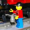
John Hill Posted September 19, 2013 (edited) Three illegal alien workers on their track speeder. This is a 12V adapted to run on the 9V track under DCC control. You can easily see the simple (i.e. crude) power pickups. The DCC decoder chip is external to the motor and hidden inside the speeder seating area, held in place with modelling clay. Edited September 19, 2013 by John Hill Share this post Link to post Share on other sites
zephyr1934 Posted September 22, 2013 @zephyr, dat would indeed be a good idea, using the PF motor and having some alternative pickup system. Not sure why one would want to use DCC than though. One could also make a radio controlled system using the same techniques. Share this post Link to post Share on other sites
Heppeng Posted September 22, 2013 (edited) Or rather than split the motor wire, get a short extension and split that instead so you leave the relatively expensive motor unaltered/unharmed. At least that is the way I do it for my PF to 12V conversions. Edited September 22, 2013 by Heppeng Share this post Link to post Share on other sites
John Hill Posted October 1, 2013 I passed a minor milestone today in that I managed to get a picture of the waveform from my sound card DCC system.. The lower trace is the output from the sound card and of course is analogue, the upper trace is the DCC digital signal as passed to the "power station" circuits. I use an LM339 voltage comparator, just one chip to convert the sound signal to digital DCC. But there is much more work required on my software! Share this post Link to post Share on other sites
kieran Posted October 3, 2013 That looks very promising Share this post Link to post Share on other sites
locoworks Posted October 3, 2013 the digitrax zephyr is a good piece of kit, you could buy a couple of cheap DC controllers and use the jump ports on the back of the zephyr allowing direct control ( for speed and direction only on the jump ports without pressing buttons ) to have direct control of 3 trains at once. alternatively buy a suitable interface and use one of the free JMRI softwares to run the zephyr from your PC Share this post Link to post Share on other sites
John Hill Posted October 3, 2013 Thanks Locoworks, I am not sure of the extended capabilities of my Digitrax Zephyr DCS50 but I do know it has the two jump ports and a couple of loconet connectors so no doubt what you say is true and thanks for reminding me. However the incentive for this project is to achieve something of my own creation. John Share this post Link to post Share on other sites
Lazarus Posted October 5, 2013 I have the Zephyr for some of my model trains its an ok start. but for the cost i would just spend the cash and get a full on command station. Issue with the zephyr is its low power output i found running locos with DCC sound this is N scale locos they would slow down when playing sounds like bells and horns. But i did buy it so i could just link it to my PC and use software to control my trains. For that i did not need a full on command station i just needed to setup a basic loco net to control remote switches and connect up my PR3. Share this post Link to post Share on other sites
roeltrain Posted October 20, 2013 Hello, I've modified the 12V gray Lego train to DCC: http://members.casema.nl/famvollaard/legotrein/index.html 3 locs run undependently. But indeed to use the numerickeypad is "difficult". I got stuck on how to use DCC + track-switching equipment, didn't know what to build+ how to configure it. Any help is welcome... Share this post Link to post Share on other sites
alainneke Posted October 21, 2013 I got stuck on how to use DCC + track-switching equipment, didn't know what to build+ how to configure it. Any help is welcome... Switches are automated with accessory decoders. These decoders come with multiple outputs (4, 6, ...) and usually send a configurable-length pulse to throw the switches. The grey-era LEGO switch motors rely on pole reversal to switch back and forth: I use an ESU SwitchPilot (with extension) to accomplish this. Wiring is a bit complicated, but described here Share this post Link to post Share on other sites
John Hill Posted June 28, 2014 Oh dear, it has been several months since I posted the wave form picture in post #16 and the software is still not ready! I got somewhat diverted onto other projects and thought it would be good to do the project in Linux. I bought a nice new PC but the installation of Linux went wrong on me.... I really must get back onto this project! Share this post Link to post Share on other sites