Hod Carrier

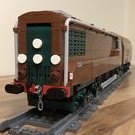
[OcTRAINber MOC] LMS Articulated Railcar (1938)

Recommended Posts

On 9/9/2022 at 2:35 PM, Darkkostas25 said:

Yeah, a lot of people underestimate the power of Teknik parts in their builds. It can provide a great solution for lots of builds.

I agree, but sometimes it can be difficult to integrate Technic parts with System bricks because it has a slightly different geometry.

On 9/9/2022 at 2:35 PM, Darkkostas25 said:

The more I look at it the more I see where also it can be used. You have done a great base for Zephir and flying hamburger or maybe for something else (I mean rolling stock of the USA and Europe).
Astonishing work! 

Thank you. That's very kind of you to say. We have seen Zephyrs and other round fronted trains down the months and years, some using different techniques. I think that what I've done is just a different approach to the same problem.

On 9/10/2022 at 4:41 PM, Paperinik77pk said:

Great DMU - the work on the "nose" is impressive - the more I look at it, the more I am amazed on how you did it!!! *huh*

Also the sides, well, are not easy at all to achieve - and again , you succeded in reproducing that shape. Great job as always!  :wub: 

Can't wait to see the "transformed" version! :thumbup:

Ciao!

Davide

Grazie, Davide. That's very high praise indeed. I'm pleased that you like what I've revealed so far and hope that the finished product meets your anticipation.

20 hours ago, zephyr1934 said:

Technic bricks pinned together can still have a lot of sag. If you want stiffness, a sandwich of three plates tall will be stiffer. That is simply a "just in case" suggestion if the technic gives you problems.


13 hours ago, Toastie said:

That is certainly true! But when you want to take advantage of the Technic bricks "hole functionality" (other than connecting them), then bracing them (two Technic beams separated by two plates + bracing part, e.g. diverse Technic 0.5 beams or even full beams) makes the "structure" vertically really stiff. At least this is what I have experienced.

I have to confess that I've not experienced problems with pinned Technic bricks sagging. The trick that I've employed is, as with all LEGO joints, a generous parts overlap and plenty of friction pins. If anything, I'm more suspicious of stacked plates as I have found that once you get out beyond a certain length the construction takes on a banana shape that means it needs securing at both ends and in the middle too. My experience is that bricks, Technic or otherwise, are far more resistant to this distortion and, because of the rigid sides, less prone to vertical flexing. I appreciate that joining bricks together introduces points of weakness where flex can creep in, which is why I try to design in such a way as to mitigate against this. Looking back at previous builds I have found that a lot of them have exceptionally strong structures. I really do build them like tanks. :iamded_lol:

In this instance, the spine is built up with plates, tiles and interior detailing and will have the various other sub-assemblies attached, either directly or indirectly, which will be stiff in other axes and add to the rigidity of the whole. I am not anticipating too many issues, but overall rigidity is in the back of my mind and I am prepared to perhaps make alterations as the build progresses to address any problems that may arise.

20 hours ago, zephyr1934 said:

How did you articulate the cars? It would be interesting to see your solution because getting sufficient clearance on curves can be tricky.

I have something that works quite well as "table scraps" but will need to be built and tested before I say anything much more about it. However, if it works as I hope it will, I should be able to run this model on tight curves (perhaps even R40s) even with the car spacing you see in the renders above.

Share this post


Link to post
Share on other sites

While I wait for the Bricklink orders to come rolling in, it's perhaps a good time to turn our attention to what happened next for the LMS articulated railcar. When we left the story last, the railcar had been stored out of use following the outbreak of war in 1939. So, what happened next?

With the end of hostilities in 1945, the railways were in a poor state and the railway companies not in any position to restart any experimental schemes that had been underway prior to the war. The main priority was rebuilding and re-establishing a peacetime economy. Nationalisation and the creation of British Railways followed soon after in order to deal with the backlog of maintenance and to make good bomb damage to the infrastructure and losses in locomotives and rolling stock.

It would seem that the newly nationalised railway had no interest in developing the LMS railcar any further, but it still remained as an asset. It was decided to convert the railcar for use as an overhead line maintenance train on the Manchester South Junction & Altrincham route, which had been electrified before the war. The advantage of using a diesel railcar rather than a steam hauled maintenance train for this purpose should be obvious.

There is not much information regarding the conversion of the railcar, and it seems to have attracted little to no attention during this phase of it's existence. The only source material seems to be an article in a 1949 edition of Railways journal, which handily survives online thanks to the LMS Carriage Association who reproduced it in an edition of their online newsletter. This contains a brief description and the only three photos of the maintenance train that I have been able to find.

The trouble with this lack of information is that it makes it hard to know how to design and build a model of it. So far, this is what I've come up with.

52366290673_b9074123ee.jpg

52366488165_a9106dab17.jpg

It looks like a totally different train, doesn't it? However, I have retained the body profile of the original as much as possible to show the family lineage.

At the moment this is very much v1.0 with a lot that still needs to be addressed. As you can probably tell, I have so far simply designed one car and copied and pasted it across to make a second to give an impression of how the railcar should look.

If you compare the renders with the photos in the article, you can see that there's going to be quite a lot I'm going to have to guess, including the colour. I've opted for dark green because that was the colour of passenger railcars (DMUs), but also because the photos show that it had a lined livery rather than being painted a plain colour. What I cannot see is the layout of the equipment below the floor or the layout of windows and doors on the second vehicle. It appears that there is a toilet because there is a window that has been whited-out, but apart from that it's hard to see anything else.

One aspect of the design which has already caused some headaches is the roof. Having a working platform on the roof means that there is a safety lip at the edges which I obviously wanted to retain, but I still needed some way of attaching the cheese slopes at the roof edges. The result of the need to use brackets meant that the roof was narrowed by half a plate at each side from 5 studs, already an awkward number, down to 4 and a bit, so I couldn't just lay tiles and call it done. It was going to need a different solution.

52366290768_11609c057c.jpg

52366063546_8f418d08ea.jpg

It took a bit of mental gymnastics but I finally arrived at a solution that I am satisfied with. Underneath it's a riot of brackets holding everything together. Apart from this, the rest of the structure is fairly conventional. Because this version of the railcar did not have the streamlined paneling, the construction of the model is very different from the original version and uses some more conventional techniques.

The lack of source information is a real issue for me in designing this version of the railcar. The photographs accompanying the Railways article are of poor quality and a very long way from comprehensive. I only have a single grainy three-quarter image of one side of the railcar and no idea of what the other side looks like. Even pre-war photos of the railcar without it's lower paneling give little idea of the layout and appearance of the underfloor equipment. The only option that I have left to me to try and gain any better impression is to take a trip up to London to visit the British Library to see an original copy of the article and hope that the photos are of better quality than they appear in the LMS Carriage Association reproduction.

To complete the story of the LMS articulated railcar, it would seem that the railcar saw little use as a maintenance train and was moved from depot to depot before finally ending up at Longsight in Manchester. Here it fell into a state of dereliction and was finally disposed of in 1967.

Share this post


Link to post
Share on other sites
On 9/12/2022 at 6:53 AM, Hod Carrier said:

I have something that works quite well as "table scraps" but will need to be built and tested before I say anything much more about it. However, if it works as I hope it will, I should be able to run this model on tight curves (perhaps even R40s) even with the car spacing you see in the renders above.

Can't wait to see what tricks you produce


On 9/18/2022 at 8:45 AM, Hod Carrier said:

52366063546_8f418d08ea.jpg

It took a bit of mental gymnastics but I finally arrived at a solution that I am satisfied with.

That makes my head hurt. But aside from the brain-strain it is looking great

Your topic has got my interest, I assume you've seen the following links,

Middle of this notes a lot of references to what appears to be a trade journal, "The Engineer, 1 April 1938." (but I bet they reproduced all of the relevant photos on the webpage). This Wikipedia page discusses the interior of the line car


Share this post


Link to post
Share on other sites
7 hours ago, zephyr1934 said:

Can't wait to see what tricks you produce

I hope I haven't over-promised and end up under-delivering. :look:  Watch this space for developments.

7 hours ago, zephyr1934 said:

That makes my head hurt. But aside from the brain-strain it is looking great

Thank you. I'm glad I could come up with something that works, but it is a fairly bulky solution that is causing some new headaches in other areas, but I'll find a way to work around those.

7 hours ago, zephyr1934 said:

Your topic has got my interest, I assume you've seen the following links,

Middle of this notes a lot of references to what appears to be a trade journal, "The Engineer, 1 April 1938." (but I bet they reproduced all of the relevant photos on the webpage). This Wikipedia page discusses the interior of the line car

I have. :grin:

The Disused Stations page is probably the best overall summary of the development of the railcar, and a bit of a departure for a site that normally focuses on stations, infrastructure and services. Of course, as this specific page relates to the history of Cambridge station and it's railway connections, it focuses on the period when the railcar operated within the area and shows photos of it there rather than elsewhere. (As an aside, Disused Stations is a brilliant website for browsing if you're at all interested in British Railway history as it documents not only closed stations and lines, but it captures former methods of working and services too. It's worth an evening just for the photos alone.)

The entry on Wikipedia takes the information largely from the Railways article of December 1949 that I linked to in my previous post. As far as I can ascertain, this is the only source of information relating to the railcar in it's later guise as a maintenance vehicle.

Luckily for me, the British Library in London hold copies of both Railways and The Engineer, as well as a few other promising titles, that may yield some more detailed information, and I will be heading up there in a couple of days to try and see them. You may well be right about the use of images from The Engineer article, but without seeing it for myself I wouldn't know for sure. I'm hoping that maybe there will be some other visuals (diagrams, drawings, etc) or at least a reasonable description that might help with the build, but I'd be happy if I only find out that I've already seen all there is to see and there's nothing more. Either way, I can get on with the design by following the information I discover or by going my own way and making something up that at least looks reasonably convincing.

Share this post


Link to post
Share on other sites

This is the point where I have to come clean and make a small admission. Prior to starting my OcTRAINber entry I had already spent several months working on another articulated train which is now an advanced work-in-progress. Therefore, a lot of the engineering decisions that I have made for that design can simply be copied across to this one giving me time and capacity to devote to other aspects of the design. Admittedly this other project has not been built yet so the LMS Railcar would act as a prototype to test these ideas. Therefore, what follows is something that I've been sitting on quietly for several months rather than the fruit of the past few weeks.

I had been applying my mind to the question of whether or not it might be possible to come up with a genuine LEGO solution for close coupling. To that end, I spent some time tinkering with some Technic elements to see what might be possible, during which I came up with the following arrangement of parts.

52373675387_c1c67d1cb7.jpg

As you can see, this arrangement permits a sort of floating pivot point along what is almost a straight line. The advantage of this is that it would permit two vehicles to be close coupled on straights but gives sufficient clearance for curves and movement of the vehicles relative to each other.

The original idea had been that this would be used for bogie vehicles. The mechanism would be mounted within the body of the vehicle with a straight bar coupler to join the vehicles together rather than a magnet as normal. Because each vehicle would centre correctly due to the bogies making reference to the track, this should not need anything additional for the geometry to work. At present, I have not had any time to build or test this idea.

The problem with articulated vehicles is that this would not work correctly since it relies on each car making it's own reference with the track. Because articulated vehicles share a single bogie, the only way to achieve this would be to have two pivot points, one per car, as quite a few builders decide to do. The downside of this is that it doesn't result in accurate movement of the train through curves and points/switches, which is something that I wanted to avoid. The majority of articulated vehicles use a single shared pivot point over the bogie which means that the cars can articulate independently of bogie and the bogie rotate independently of the cars. So how am I going to make the cars centre when there is nothing to apply the relevant force?

52373673567_f598ac7eef.jpg

Simple. I use a rubber band which pulls the end of the mechanism back towards the chassis centreline.

52374619716_c1712e1153.jpg

Two cars coupled. The bogie is pivoting around a 5L Technic beam, which is conveniently hard to see because it's black, which forms the bar coupling between the cars. You can see the offset in the mechanism due to the articulation between the cars. Articulation and bogie rotation work independently as intended. A quick spin around a test track shows that it's working just as I hoped it would, with everything running nice and smooth. It even copes well with LEGO's horrible R40 curves. I'm just hoping that adding weight to the cars as they are built up does not negatively impact on this.

On the downside, the use of rubber bands does now mean that this is a mechanism that will require servicing from time to time as the bands perish and need replacement. The other aspect of this which I think is a bit of a shame is that this is the sort of thing that's quite clever but, because it works well, is likely to go almost totally unnoticed when the railcar is finished.

Share this post


Link to post
Share on other sites
40 minutes ago, Hod Carrier said:

On the downside, the use of rubber bands does now mean that this is a mechanism that will require servicing from time to time as the bands perish and need replacement.

Brilliant - as expected - solution. What else ...

With regard to the rubber bands: The LEGO varieties (red/blue/yellow/white) "live" much, much longer than the household-type bands. Do you see any chance to use e.g. the red one? It will expand the service interval significantly. I experienced that on the "Technic" Star Wars series droids. They came with the cheap black bands - upon replacing those with the mentioned bands, they still stand tall on their shelf ;)

Thanks for sharing and all the best,
Thorsten

Share this post


Link to post
Share on other sites
12 hours ago, Hod Carrier said:

The other aspect of this which I think is a bit of a shame is that this is the sort of thing that's quite clever but, because it works well, is likely to go almost totally unnoticed when the railcar is finished.

That's great engineering for you. It makes things look easy, effortless.

I love this solution!

Share this post


Link to post
Share on other sites
On 9/21/2022 at 9:11 PM, Toastie said:

Brilliant - as expected - solution. What else ...


On 9/22/2022 at 8:42 AM, Duq said:

That's great engineering for you. It makes things look easy, effortless.

I love this solution!

Thank you, gentlemen. This is the aspect of the design that I feel proudest of, and the one that I think has the widest possible applications by other builders.

On 9/21/2022 at 9:11 PM, Toastie said:

With regard to the rubber bands: The LEGO varieties (red/blue/yellow/white) "live" much, much longer than the household-type bands. Do you see any chance to use e.g. the red one? It will expand the service interval significantly. I experienced that on the "Technic" Star Wars series droids. They came with the cheap black bands - upon replacing those with the mentioned bands, they still stand tall on their shelf ;)

I suspect that I bought the self-same Star Wars droid set myself and am aware that not all LEGO rubber bands are made equal. The glossy ones are of a different material which makes them less prone to perishing. Sadly I didn't have any short enough for this application, but they are on my list of future upgrades. :thumbup:

Share this post


Link to post
Share on other sites

You have been working the black magic of mechanical engineering you have, and I must say, you have become quite the dark wizard. Completely inconceivable design.

Share this post


Link to post
Share on other sites

@Daiman @zephyr1934 Thank you for the amazing feedback. I certainly feel as though I'm pushing myself with this build, and so far it's going as well as I could have hoped.

@Toastie I have made some alterations and upgraded the bands to the white LEGO bands, as well as making them easier to access for servicing. Mind you, at about 1GBP a go they'll need to last a looooooong time to be better value than the ordinary garden variety rubber bands. :look:

It's been a little while since I updated folks on the progress of my build, so I thought I should correct that oversight.

A couple of weeks ago I took a trip up to London to visit the British Library. This is an amazing institution that holds all manner of weird and wonderful items, including copies of pretty much every book, magazine and journal available in the UK going back many many years. This is really the only place where I could expect to see original copies of the primary sources used in the online articles I had been reading and would give me the best chance to get more details that could help me complete my builds. My expectation was tempered a little in the knowledge that probably the majority of detail and the best of the images had already been reproduced online. I wasn't anticipating a massive revelation.

And so it proved. There were no huge surprises to be had, but I did manage to meet one of my targets, which was to see if the photos in the original article concerning the rebuild of the railcar were better than the online reproductions.

52404346158_164a8f9d03.jpg

Railways: December 1949

This image does show details that the online reproduction does not, but it is still very vague. However, I can at least now read what it says down the side of the cars which I couldn't before, so I think I can call that a win.

I've also been making progress with building the original version of the railcar.

52404346128_29a056ae1b.jpg

Chassis and interiors for the non-motor end car and the centre car have been completed.

52404346018_9e46160ff8.jpg

The centre car is what is referred to in the UK as a composite coach in that it contains both 1st and 3rd class open saloons. This is the 3rd class area with the toilet cubicle and a small luggage rack opposite.

52403337142_f65f3fd9aa.jpg

The posh end. I've had to use some creative techniques to fit some semblance of seating around the various chassis structures. I've used trans-clear parts to try and minimise the visual impact of this.

52403846731_84a46a8a40.jpg

I've also built the roofs. There's some colour variation in the parts, but that can be explained away as weathering.

52404133604_4b77578724.jpg

The shaping of the transition between the roof and the bodysides is just as I'd hoped and the structure remains strong.

Construction has been slower than I would have liked. The problem is that having a deadline by which I need to have completed not one but two builds means that I have not had my usual tinkering time to review the design and make sure that everything goes together as it should. As a consequence, I have been having to make alterations as I go, which means ordering parts and waiting for deliveries before I can move on to the next stage. I also still have the design of the second version of the railcar to complete, parts to order and the build to commence. Juggling these two projects along with work and other real-life commitments means that the pressure is starting to build. Four weeks should be enough time, but it might be a bit close.

Edited by Hod Carrier
Bad spelling (thanks @Toastie)

Share this post


Link to post
Share on other sites
2 hours ago, Hod Carrier said:

52404133604_4b77578724.jpg

The shaping of the transition between the roof and the bodysides is just as I'd hoped and the structure remains strong.

Smoooooooooth!

Share this post


Link to post
Share on other sites
8 hours ago, Hod Carrier said:

BGP

What is a BGP? :pir-look:

:pir-huzzah2: to your fantastic progress!!!

Best,
Thorsten

Share this post


Link to post
Share on other sites

@zephyr1934 @Toastie Thank you, gentlemen. There's still a long way to go but I'm pleased with how things are progressing so far.

38 minutes ago, Toastie said:

What is a BGP? :pir-look:

It's a British Great Pound. :grin:

I think my spill chequer got involved without me realising and messed things up. :hmpf_bad:

Share this post


Link to post
Share on other sites

While I wait for parts to arrive so that I can continue with the build of the original version of the railcar, it's time I devoted some attention to it's second incarnation. Time is marching on, and I can't afford to be lazy.

As you may recall, in 1949 the LMS railcar re-emerged in a totally new guise as a maintenance vehicle for the repair and upkeep of the overhead power lines on the line between Manchester and Altrincham. In order to be useful for this purpose, the railcar underwent a radical rebuild with new cabs, new roof, new interior arrangement and one less car. The problem is that, apart from a single short article that appeared in the journal Railways in December 1949, this transformation appears to have gone totally undocumented. Not only that, but in the time between it's conversion and disposal in 1967 it seems to have attracted virtually no attention whatsoever. As far as I am aware, the only images of this train that exist are the three poor quality black and white images that accompany this article. To date, these are the only images that I have discovered.

This causes something of a problem when trying to create a model of it. The photos do give an impression of the overall look, but it's very hard to make out any details, even for fairly major things like doors and windows. The description of the train says that one car was converted to a mobile workshop while the other provided mess facilities for the crew, but it's not even possible to say which car was which. I can't even be certain what colour the train was. All I know is that the two cars were different and then had to base my design decisions around hints and suggestions that I can discern from the poor images. I'm just glad that the article held in the British Library was of better quality than it's online reproduction.

So anyway, with the excuses out of the way, this is what I have come up with.

52406764562_f087754e8f.jpg

This render show approximately the same aspect as the main photo in the article which means that you can compare them for yourselves. It's a little hard to see the window positioning, but then that's also the case with the photo of the real train. I've guessed at the livery being dark green as that was the colour for passenger railcars at around the same time.

52407553359_e48ea00e03.jpg

The railcar was accompanied by a wire wagon, that was itself a repurposed redundant vehicle. This must have been quite a survivor even at this time, as it was converted from a Midland Railway 6-wheel 30 foot coach, a type that was being built around the turn of the 20th century.

I've been able to get good source material for the chassis and running gear, but everything above chassis level is an educated guess. In the photo, the wire wagon is at the rear of the railcar and, therefore, the image of it is incredibly poor. Plus, the vehicle is covered with a wagon sheet which hides everything. However, from the shape of the wagon sheet it is possible to tell that it had low sides and a central sheet hoop but, on the downside, it hides everything else. I have opted to model three cable drum stands, but in truth I could be way off.

52407703325_d74a76317c.jpg

Other details that I've had to guess at include parts of the railcar itself. In the article photo, there appears to be a recessed feature towards the far end of the second car but no clue as to what it might be. It could simply have been an open door, but the feature appears to extend all the way to the roofline. It's possible that it is vents and exhaust for the onboard generator. I have opted to model it as a ladder for access to the roof to match a similar one at the centre of the railcar. I may yet change my mind about this.

Given that the photo shows only one side of the railcar, I have opted to make my model symmetrical. It's not necessarily likely, especially for internal user stock like this, but without any visual sources I have no way of knowing. At least replicating what I can tell from the side that it featured saves me the trouble of having to imagine what it looks like on the other side.

I suppose that one good thing about not having any visual sources is that no-one can tell me that I've got the design wrong. LOL!!

Share this post


Link to post
Share on other sites

Both versions are cool and neat.  And I LOVE the usage of Jacobs bogies and the overall shape of wagons! They are marvelous ! Astonishing work! 

Share this post


Link to post
Share on other sites
On 10/5/2022 at 6:45 PM, Hod Carrier said:

This causes something of a problem when trying to create a model of it. The photos do give an impression of the overall look, but it's very hard to make out any details, even for fairly major things like doors and windows. The description of the train says that one car was converted to a mobile workshop while the other provided mess facilities for the crew, but it's not even possible to say which car was which. I can't even be certain what colour the train was. All I know is that the two cars were different and then had to base my design decisions around hints and suggestions that I can discern from the poor images. I'm just glad that the article held in the British Library was of better quality than it's online reproduction.

Sounds like glass half full or half empty. In this case you could claim that it is a perfect reproduction and there's nothing out there to prove you wrong (grin)

Share this post


Link to post
Share on other sites

@Darkkostas25 Thank you. I had to work hard to get the shape as I wanted it, but I think the efforts have paid off. I'm hoping to have a complete car ready to show very soon.

@zephyr1934 That's exactly the approach I'm taking. :wink:

Share this post


Link to post
Share on other sites

I've been following the topic here as a silent reader since the beginning, but it probably needs to be said: Top!

Especially the old version with the pulpit I find really well done. Construction-wise, this is a masterpiece.


Thomas

Share this post


Link to post
Share on other sites

It's been a little while since posting any updates on my progress. Partly this is due to being busy with real-life but also because I've been up to my eyeballs with two large builds. As a result, I haven't really had any time to keep you all abreast of changes.

The build of the original version of the railcar has been progressing. Due to the time constraints imposed by the contest deadline I did not have my customary "tiffling time" to make sure that the design was good before progressing to the build. Instead, alterations have been needed to be made as the build went along which meant that I could only make progress in fits and starts.

Luckily the number of changes that needed to be made were small and primarily structural rather than cosmetic in nature, but it did mean that I could only progress so far and then have to stop and wait while new parts arrived. In the meantime, I was able to continue with the design of the second version of the railcar and to order the parts I need.

The alterations made were to strengthen the bogies, reinforce the centre of the cars around the door opening and to change the close-coupling design to make it easier to access from below should rubber bands ever need to be changed. Otherwise, the appearance of the railcar is almost completely unchanged from the design renders posted so far.

So how does it all go together? Well, as outlined previously, the idea is that the cars are made up of various sub-assemblies clipped to a chassis. The main assemblies are the lower panels, the upper panels, the passenger doors and the roof.

52440074170_cd8bd11956.jpg

This is the centre car broken down into its various sub-assemblies. The upper and lower panels are clipped on to attachment points while the doors and roof are fixed conventionally.

52439894089_25f0be9a0e.jpg

With all the parts assembled, this is what the centre car looks like. I think it looks quite good and shows off the curved profile quite well, plus it is remarkably sturdy with all parts assembled, which has been a very nice outcome.

52439149167_020e71de8b.jpg

Looking through the car end it's possible to get an appreciation of the profile as well as showing the close-coupling.

I've also completed the end cars too, including the motor coach. With the roof off it's possible to see the technical arrangements inside.

52440139493_dbd59b0c27.jpg

I wanted to use a train motor for this build in order to give it a good turn of speed but, being a 7-wide design, I didn't feel it appropriate to use it in the normal way. The problem is that it is rather a large lump and would result in the bogie being waaaaay too big. So as a solution I have placed the motor inside the body instead and have it driving a conventional Technic bogie to get the power down to the wheels.

52439115622_e9073e2fe2.jpg

Roof on and this is how it looks. I think it's turned out very nicely and shows a very good likeness to the renders.

I always worry a little with Stud.io that it allows for tolerances that real bricks do not, so I was very careful to try and make sure that I didn't take too many liberties with them. However, I was still a bit nervous about how well this part of the build would go. A small strengthening issue aside, I was pleased to see how well it came out.

52440139123_a2969c0312.jpg

I will confess to having used a small amount of coloured vinyl to carry the shape of the livery around the front of the train, but I didn't really see any alternatives. LMS lettering, numbering and crests are courtesy of my old nemesis, waterslide transfers.

So, what's next? Apart from having to build a whole other version of this railcar, I will still need to test run this model to ensure that it works as I hope it will. The close-coupling is a source of worry, as I'm unsure how well it will work. Remember, this wasn't something that I thought would be usable for articulated vehicles like this. However, a quick test suggests that it will (just) squeak around R40s without derailment.

Another challenge will be to try and work out how and where I'm going to photograph this beastie, as it's quite a bit bigger than the majority of my builds. But for now, I think I'll just have a cuppa, sit back and enjoy looking at it.

Share this post


Link to post
Share on other sites
2 hours ago, Hod Carrier said:

I think it's turned out very nicely and shows a very good likeness to the renders.

What? You think?

No.

>It turned< out nicely - and given the amount of work, you put into the virtual construction: It was to be "expected" - as far as I am concerned, looking at what you have posted here (I am only "here") before.

(I know, I know ... we do a lot of "simulations" prior to/along with experimental lab work, and/or to validate lab results, and/or, and this is the thing, to use validated model results for experimental design. Experiments are usually expensive, as is LEGO. This approach needs of course a powerful modeling software - let's say Stud.io - a carefully designed model - AND a highly qualified, experienced modeler, otherwise you can't come up with a carefully designed model in the first place :pir-sweet: ... and validation, and I guess this is what you have done in the past ...)

But honestly: With your experience, the model looked - to me - "validated". An experienced virtual modeler does not use "Siemens air hooks or anchors" :pir-laugh: to fake it work. They know better.

Again, but with deep appreciation: Congratulations!

Honestly, I can "see" you sitting back. With a smile in your face that is - subtle. More in the eyes than in your face.

And of course: A slight bow. Hopefully remotely matching your smile.

All the best,
Thorsten

Share this post


Link to post
Share on other sites

@Toastie Sir, you are too kind with your praise. Thank you so much for your kind words.

I do feel as though I'm on a journey with LEGO and am still gaining experience. Certainly my knowledge has increased over the years I've been doing this, following the examples of others more experienced and skilled than me and applying the techniques they have shared to my own designs. Familiarity with the palette of parts and the introduction of new items has made things possible that before were hard to achieve.

As I think you know, my approach is to design virtually first and then in bricks once I'm happy with how things look. But, as you say, there are no sky hooks or magic super-strength 1 stud connections, and I'm always thinking about how to realise it in real brick, so strength and stability is always at the front of my mind. The problem is that Stud.io et al do not always highlight where you've made a mistake because they permit the use of magic gravity-defying parts and so on.

In the case of this particular build, I felt as though I was pushing the boat out further than the limits of my experience by using techniques on a scale that I have never attempted before. Consequently, I was unsure how strong the overall structure would be, whether there would be any weak connections or whether the overall weight of the cars would be too much for the structure and cause distortions and, as mentioned above, how well the close-coupling between the cars will work. There were a few areas that needed improvement that only came to light by snapping parts together. I may have spotted them prior to building if I'd had my customary "tiffling time", but the constraints of the competition do not permit me that luxury and so I have to find them the hard way.

13 hours ago, Toastie said:

Honestly, I can "see" you sitting back. With a smile in your face that is - subtle. More in the eyes than in your face.

I called my Mum on the phone last night for a chat and had the railcar sat on a length of track on the coffee table and just kept on looking at it while we chatted away. Being able to sit back and enjoy the completed build is immensely satisfying. I just have to work out how and where to photograph it so that I can share it with you and everyone else.

Share this post


Link to post
Share on other sites
On 10/19/2022 at 1:39 PM, Hod Carrier said:

I wanted to use a train motor for this build in order to give it a good turn of speed but, being a 7-wide design, I didn't feel it appropriate to use it in the normal way. The problem is that it is rather a large lump and would result in the bogie being waaaaay too big. So as a solution I have placed the motor inside the body instead and have it driving a conventional Technic bogie to get the power down to the wheels.

*huh*


Looks amazing, the curves are impressive

Share this post


Link to post
Share on other sites

Thank you so much, @zephyr1934. I'm definitely enjoying having it sat on my coffee table.

I know that my use of the train motor is a bit unusual, but I really couldn't see any other way. It would be fine for a loco which generally have much larger bogies, but for a railcar it would just have been way too big. That said, I wanted the model to have a decent turn of speed as befits a passenger train. The only alternative would have been to gear-up some manner of Technic motor, but that would have been more complex and at least as space-hungry as the solution I picked.

----------------------------------------------------------------------------------------------------------------

With the original version of the LMS railcar taking all the limelight, and time fast running out, it's finally time to turn my building ray on the second version. Just to recap, the railcar was rebuilt into a maintenance vehicle for overhead power lines around Manchester and spent the remainder of its life in that area. The rebuild saw the train lose the centre coach and gain some new features that rendered it almost completely unrecognisable from its original form.

52443644512_32113f1ea1.jpg

The design of this version is very different from the original and is, if anything, a bit more conventional. Rather than having a chassis with the body assemblies clipped onto it, this design uses a "bath-tub" chassis made up of bricks and plates which gives it a huge amount of strength and rigidity.

52444160086_b451e5296f.jpg

Where things get a little less normal is with the roof. The desire to keep the roof to a certain width meant that I could not simply build it flat, but rather had to use quite a lot of brackets with plates and tiles at right angles to each other to get the required width. This is a quick look at the underside of the roof which gives an idea of how it's been done. There is a slight structural weakness which I know how to address, but the proximity of the deadline means that I probably will have to come back and deal with it after the close of the contest as I really don't think I'll get the necessary parts in time. I don't think it will cause too many issues when mated to the bodyshell, but time will tell.

52444602240_4ea605eefb.jpg

Speaking of the bodyshell, I have decided not to bother trying to make an interior. There are so few sources of information that it's not even possible to tell which car served what function, but I think that will be OK given the lack of windows.

52444436004_e12f172d87.jpg

The front of the maintenance train tapers down to 6-wide and contains plenty of windows to help the crew position the train accurately when it was in use. It's quite a plain and functional design. The black cylindrical part is the roller that would carry the cables for the overhead power lines up and over the cab so as not to cause any damage to the train.

As can be seen, there's still plenty of work to do before this model is complete, but it's coming together very nicely. I am still awaiting the final few parts to arrive through the post, including the all-important ladders which are coming from overseas. I trust that they will get here in time, but I am starting to feel the tension a little bit. There were one or two areas where I felt I was making some compromises in the design, particularly with regard to strength, but it's actually holding together quite nicely. I hope this can continue, as I won't have enough time to make any changes to the design if I'm to hit the deadline.

Edited by Hod Carrier

Share this post


Link to post
Share on other sites

Create an account or sign in to comment

You need to be a member in order to leave a comment

Create an account

Sign up for a new account in our community. It's easy!

Register a new account

Sign in

Already have an account? Sign in here.

Sign In Now

  • Recently Browsing   0 members

    No registered users viewing this page.