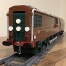
Hod Carrier

[MOC] Differential Drive - Variable Reduction Gearing

Recommended Posts

I’m very cautious of using the word “new” to describe anything I do because I know that in LEGO, as in life, there is very rarely anything completely new under the sun. With that in mind I will just preface this thread by saying that this is not something that I have seen done elsewhere, so I’m going to bring it to the attention of the community. But first, a little diversion by way of explaining where my inspiration came from.

I had been doing some reading about British Railways No 10100 which is better known as the Fell Locomotive. This was a prototype 2-D-2 locomotive that was perhaps the oddest (and oddest looking) loco to have graced the UK rail network and was an attempt to build a 2000hp mainline diesel engine using a mechanical transmission.

Most mainline diesel locomotives use either electrical or hydraulic transmissions which are better suited to coping with the high power demands of mainline use, with mechanical transmissions usually used on railcars and small shunting locos. However, the Fell Locomotive took a different approach using four 500hp V12 engines mated to a transmission which utilised differential gears. Not being very mechanically minded I had no idea what this meant or how it worked, but then I happened across this old newsreel hosted on another forum which explained things in layman’s terms and the scales fell from my eyes.

The transmission was brilliantly conceived and it is clear how it would suit the needs of mainline operation. But then I had a Eureka moment and realised that this might work well in a LEGO loco too. Well, not the whole four engines and three differentials thing, but with two motors and a single differential it might be possible to increase the controllable range of speeds achievable.

The original idea was to have a sort of two-speed loco that could run at half it’s normal speed with a single motor and then access the rest of it’s performance with the second motor, but then I realised that by altering the speed and direction of rotation of the motors relative to each other it would be possible to almost infinitely adjust the loco’s gearing. Suddenly I was looking at the possibility of running models that could do low speed as well as high speed without having to make compromises with the gearing.

So for the past few months I have been working on a couple of prototypes. The first is a rebuild of my own English Electric GT3 4-6-0 and the second is a modified version of @Commander Wolf’s bijou little Fairbanks Morse H10-44 switcher. Each loco would have a different motor and gearing arrangement to test how they work with different types of loco design.

This is the new power arrangement for GT3. There are two L-motors in a stacked arrangement with gearing to take the power to each end of the differential. The gearing gives a final ratio of 1:2 which, when added to the model’s XL drivers, should give a decent increase in speed.

51232806619_26c32f3b78_z.jpg

51231988326_21d1d7e35c_z.jpg

The H10-44 has a slightly longer geartrain due to the need to power both bogies. This loco use a pair of M-motors placed at either end of the differential. The model was built with the option to alter the final ratio by sliding the relevant sized gears along the driveshaft to engage with the differential, with either 1:1 gearing for some proper slow speed switching capability or 1:3 for higher speed running.

51233092755_8ef95b4658_z.jpg

51232778849_2a107b6f7b_z.jpg

The gearing arrangement that allows for these two different final ratios is quite simple and can be achieved without any major rebuilding, as the shaft arrangements are identical.

51232319973_66df3185e1_z.jpg

As well as the physical arrangements of motors and gears that were necessary, to get the best out of the system I decided that I would also need some form of control. I suppose that, if you were dexterous enough and deft at using one, it could be done manually using a remote, but I didn’t think that I could manage that. I opted to use Powered Up as this has been the de facto hardware for a while now, but you could use any system you like.

As it doesn’t appear to be possible to share Powered Up profiles I have given a full description of how I built the custom control profile, but I have hidden it as a spoiler so that those who have no interest can easily skip on ahead.

Spoiler

The first thing to do was to work out how the motors would work with each other in order to drive the model as I intended. Using a spreadsheet I was able to come up with a motor map that looked reasonable. The graph below shows it in graphic form.

51232271248_26dab24a0c_z.jpg

One thing I wanted to try and do was to keep both motors working at not less than 50% power/speed in order to try to avoid a motor stalling due to low power input.

Having come up with the motor map it was time to translate this into a control profile.

51219925641_ca6f36d360_z.jpg

The user interface to control the trains. It's fairly self-explanatory I should think.

Button 1 increases power/moves the model forward, button 2 decreases power/moves the model backwards and button 0 is the emergency stop. Dial 3 in the centre is the train speed while dials 4 and 5 show the motor speed for each motor.

51234855336_9b157779b6_z.jpg

This is the program in it’s entirety.

51234835791_9a018dc24a_z.jpg

These blocks control the front end which affect the behaviour of the buttons and dials and sets variable "a" which is the train speed.

The three blocks on the left are the controls for the buttons. The train speed is increased and decreased in steps of 10 out of 200. The wait block sets the minimum time between button presses, which I have set to 0.1 seconds. The other two blocks on the top line set the maximum and minimum train speed as 200 and -200, so that no matter how many times the buttons are pressed these limits are not exceeded.

The remaining three blocks are for the dials. Because the range of "a" is 200 to -200, this variable is divided by 2 as the dial generally works best when it shows a range of 100 to -100, so this ensures that the reading is compatible.

51232355238_b4461125fb_z.jpg

These blocks calculate the values of "b" and "c", which are the variables used as motor power/speed inputs. It looks a bit complex, but the basic idea is that this code replicates the motor map to give the train it's range of speed.

51232355163_aa8e0741d0_z.jpg

Finally there are the motor blocks. These are the blocks used for simple linear motors that do not have an in-built rotation sensor. Quite simply, variables "b" and "c" are fed into the motors.

It may be necessary to invert the input for one motor depending on how you arrange the gears within the model. Generally this would be the case if you place the motors at the opposite ends of the differential. To allow for this, I have multiplied one of the motor inputs by -1 which will reverse the direction of the motor.

51224035014_0c06e93558_z.jpg

During testing I discovered that there was a problem with using the relevant code to control motor speed when using motors with in-built rotation sensors. This feature would have been very useful to ensure the correct speed of each motor relative to each other as well as helping to overcome friction, but it could not be made to work. It seems that there is an issue with the firmware on the 2 I/O City Hub (PN:88009) which prevents this from working as it should (more information in this thread).

To get around this, I came up with this solution which is in the form of a feedback loop to adjust the motor power based on it's speed. It's not a perfect solution, but it seems to work well enough.

With models and a control profile built it was time to go testing. Here are a couple of videos of the two prototypes strutting their stuff. Each one accelerates slowly up to maximum speed before slowing to a stop. (Apologies for the quality of the video. Unlike the SBrick app, the Powered Up app doesn't have a "set and forget" feature, which means that I've had to resurrect an ancient digital camera to record these videos.)

51231960991_e5670e18e0_z.jpg

51231259372_74ff22467f_z.jpg

The H10-44 is running a 1:1 final ratio as I discovered that even with two M-motors there just wasn’t enough torque to turn the higher 1:3 gearing. Even when it could be persuaded to move the performance was erratic as often one motor would stall even at high power input levels. It’s much happier running with the 1:1 gearing, which is appropriate for a switcher.

GT3 benefits from having more power thanks to the L-motors and a degree of intelligence due to the in-built rotation sensors on the motors. This means that the motors can adjust the amount of power they need depending on how their speed compares to the input values from the control profile. As such it shows a good range of speed and is able to maintain that speed even when taking tight bends. The Powered Up app still isn’t especially stable when controlling the L-motors and will sometimes drop the connection to the hub, but it doesn’t happen every time so I can live with it.

So what are the negatives? Well, you need to have two motors and enough space inside your model to take advantage of this, but dual motor set-ups are fairly common in train builds these days. Also, the longer and more convoluted drivetrain is bound to generate more internal friction and battery life may be reduced due to the greater demands.

I still have more things that I would like to try. In particular, I’d like to uprate the H10-44 with some L-motors and see if it can manage the 1:3 final ratio. I’m sure that there are some tweaks to be made with the control profile too to give better control and flexibility. But as I’ve been talking non-stop for such a long time I think it’s time for me to shut up and hand over to you for questions, comments and feedback good and bad.

Edited by Hod Carrier
Updated images

Share this post


Link to post
Share on other sites

That GT3 running looks pretty impressive, is that running the 1:3? And are you using any type of lubricant? So far my two attempts at just running power through gears have made me simplify everything down to as few gears as possible to prevent friction or stripping, so this just looks crazy to me, but I am working on a 2 motor 4-6-4 so it's also intriguing. Now I gotta hit bricklink and see if I have anything with that differential piece in it, lol.

SD

Share this post


Link to post
Share on other sites
3 hours ago, SD100 said:

That GT3 running looks pretty impressive, is that running the 1:3?

Thanks very much. :classic:

51231988326_21d1d7e35c_z.jpg

The final gear ratio for GT3 is actually 1:2 thanks to that little 12T bevel gear at the bottom. The problem is that I chose to modify an existing model rather than design and build one from scratch, so it's a bit of a compromise. It needed an additional gear to reach down into the chassis and the spacing meant that only the 12T would work. But I'm not disappointed because it has XL drivers so is already geared up a fair bit, so 1:2 works quite well.

3 hours ago, SD100 said:

And are you using any type of lubricant? So far my two attempts at just running power through gears have made me simplify everything down to as few gears as possible to prevent friction or stripping, so this just looks crazy to me

Not at the moment, no. I only run trains occasionally for my own pleasure so wear isn't a major concern for me. I would expect that those folk who run their models for extended periods (e.g. at exhibitions) are used to the need to carry out loco maintenance including the servicing and renewal of the geartrains, and this will be no exception.

In principle I do agree that you want to keep your geartrains as short and as simple as possible, but for a system like this there really isn't any alternative. Even with some of the aftermarket controllers that have different power modes you still have the limitations of the motors themselves and a fixed gear ratio.

I have found that you want to try and keep things as robust as you can to prevent slipping, and the L-motor certainly has enough torque to separate bricks.

3 hours ago, SD100 said:

I am working on a 2 motor 4-6-4 so it's also intriguing. Now I gotta hit bricklink and see if I have anything with that differential piece in it, lol.

I'm looking forward to seeing it finished. :thumbup:

Share this post


Link to post
Share on other sites

That's brilliant! The FM switcher looks really sharp and the GT3 looks fascinating (and at top speed looks like it could hop off the tight curves). The operation is also impressive, that's a crazy amount of work you put in.


16 hours ago, Hod Carrier said:

So what are the negatives? Well, you need to have two motors and enough space inside your model to take advantage of this,

I would presume that is one of the factors that kept the Fell Locomotive from going any further, I would imagine standard maintenance on side by side diesel engines is a lot harder than when you can access a single engine on both sides.

Share this post


Link to post
Share on other sites

Wow! Congratulations @Hod Carrier!

From the loco, the drive train, to the software solution: Simply brilliant! I love to see ingenious hardware solutions combined with smart electronics/software - and all completely in true LEGO space!

Seeing an engine or a whole train moving that slowly and without stuttering ... wonderful.

[Just as information: In the "other thread" dealing with the buggy SetSpeed command you found on the City hub in conjunction with smart motors, things are clearing up as well]

Thank you very much for your time writing this up so nicely and sharing all the information!

Best regards,
Thorsten

Share this post


Link to post
Share on other sites

Nice technique demo, very well elaborated.
For me, it is not the first known to me locomotive with 2 motors and differential for different speeds (there was a China brick manufacturer rather), but you still had the idea. I "know" the set only from videos and do not have it (do not want it either ;-) ).

What I see as a problem:

2 PU L- motors to a City-Hub draw too much current, the HUB is constantly in overload flashing. You can also see in the video.


I had also tried a locomotive with 2 PU L-motors on the City Hub: was not good.
- Akkus weak
- Batteries immediately empty and could not bring their higher voltage

The PU-L motors draw a lot of current. Two of this are too much for one HUB.

Thomas

Share this post


Link to post
Share on other sites
10 hours ago, zephyr1934 said:

That's brilliant! The FM switcher looks really sharp and the GT3 looks fascinating (and at top speed looks like it could hop off the tight curves). The operation is also impressive, that's a crazy amount of work you put in.

Thank you. Credit for the H10-44 has to go to the original designer, as there's still rather a lot of his design still in my model. I have made some changes to facilitate the different drivetrain and a few other cosmetic tweaks, but the cab, bogies, platforms and the overall size and shape are still faithful to the original design. GT3 looks like it's approaching train motor speeds but luckily it stuck to the R40s even flat out. I'm feeling very pleased with the results so far, even if the performance from the M-motors has been a little disappointing.

10 hours ago, zephyr1934 said:

I would presume that is one of the factors that kept the Fell Locomotive from going any further, I would imagine standard maintenance on side by side diesel engines is a lot harder than when you can access a single engine on both sides.

It lasted a remarkably long time in frontline service in spite of being wildly non-standard, although I've no doubt that it did so largely thanks to good manufacturer support due to it's highly complex nature. There were reports that an improved version was on the drawing board, but it was not pursued. More about the Fell Locomotive can be found in the usual places.

9 hours ago, Toastie said:

Wow! Congratulations @Hod Carrier!

From the loco, the drive train, to the software solution: Simply brilliant! I love to see ingenious hardware solutions combined with smart electronics/software - and all completely in true LEGO space!

Seeing an engine or a whole train moving that slowly and without stuttering ... wonderful.

Thank you, Thorsten. I wanted to try and keep it all LEGO as much as I could and the combination of hardware and software is what made the results possible. LEGO isn't a brilliant medium for railway modelling due to the limited capabilities of the motors that we're given to play with, and I think that train builders push them further than almost any other segment of the LEGO modelling community, so it's nice to be able to showcase just what they can be capable of with a bit of thought. I've not tried pulling any load behind either loco yet, so I just hope that the smooth motion can continue even with a tail load.

9 hours ago, Toastie said:

[Just as information: In the "other thread" dealing with the buggy SetSpeed command you found on the City hub in conjunction with smart motors, things are clearing up as well]

[I'll take a mosey over there shortly and have a look and see the progress. I did e-mail LEGO customer service as you suggested but have only had the usual "thanks for your enquiry" response so far. I'll update the community of any news I receive.]

9 hours ago, Toastie said:

Thank you very much for your time writing this up so nicely and sharing all the information!

You're really most welcome. I wanted to share all the information to make it easier for others to replicate what I have done if they wish to.

9 hours ago, Ts__ said:

Nice technique demo, very well elaborated.
For me, it is not the first known to me locomotive with 2 motors and differential for different speeds (there was a China brick manufacturer rather), but you still had the idea. I "know" the set only from videos and do not have it (do not want it either ;-) ).

Thank you, Thomas. I did think that I would not be the first to have this idea.

I have seen comments about using a differential, but only as a means of equalising the power from two motors driving the same geartrain and not with independent motor control in the way that I have done. Likewise I am not familiar with these other sets and don't know how they used the motors and differential. Is it similar to this design with independent motor control?

9 hours ago, Ts__ said:

What I see as a problem:

2 PU L- motors to a City-Hub draw too much current, the HUB is constantly in overload flashing. You can also see in the video.

Isn't the flashing orange light a low battery warning?

9 hours ago, Ts__ said:

I had also tried a locomotive with 2 PU L-motors on the City Hub: was not good.
- Akkus weak
- Batteries immediately empty and could not bring their higher voltage

The PU-L motors draw a lot of current. Two of this are too much for one HUB.

For sure!! If I'm getting the low battery warning already after just a small amount of testing so far then it's clearly draining them fast. I should just mention that I used the same hub and batteries for all tests with both locos so far, which includes static and dynamic testing. At the moment I'm using normal Duracell AAA disposable batteries but I am planning on modifying the hubs to accept a Znter rechargeable PP3 9V battery instead which should provide the full 9V until discharged. It may not improve battery life but it might help ensure consistent performance.

**EDIT**

I need to draw your attention to the fact that I've had to change a couple of the images of the code used for the PUp custom controller due to posting incorrect details. Unfortunately the images did not match the descriptions given, but I have now changed the images in the original post to make sure that they are correct. Anyone looking to replicate the code will need to check again to make sure they have the right information.

Edited by Hod Carrier
Updated Info

Share this post


Link to post
Share on other sites

Regarding the differential: I fear this is cool, but most often pretty pointless. The main advantage in using two motors in this way is to counteract motors that have different speeds. This might be because you cannot synchronize them or if they have variances due to low manufacturing standards or aging (or simply being completely different motors). I would guess that for two TLG motors (of the same kind), the loss from friction in your construction is probably higher than any friction due to manufacturing variance in the two motors.

Some third parties have larger variance in motor speed, so for those, using a differential makes sense. I recall that the (already mentioned) QJ steam locomotive only has a RC remote control that can only toggle motors on and off: Thus their differential makes it possible to run at two different speeds instead of just one. For PU-motors (L- and XL at least), you actually can run them synchronously, so the friction with differential would simply be larger than without.

If you would add a "high" gear ratio two the motors before they hit the differential, it would make a difference: You then could use one motor for high torque, low speed; the other would then supply low torque and high speed.

tl;dr: Cool but only useful for bad motors or simple remotes. Or if you add differing gear boxes in between the motors and the differential.

Share this post


Link to post
Share on other sites
9 minutes ago, Black Knight said:

I fear this is cool, but most often pretty pointless. The main advantage in using two motors in this way is to counteract motors that have different speeds.

But wait: This is not what @Hod Carrier is doing here, as far as I understand Fell's gearbox principle: I thought that the "trick" is that you have n motors; and you can consecutively or in parallel switch them on and off without the need of a clutch as you see fit. It is more of a "clutchless" gearbox rather than anything that synchronizes individual motor speeds. I bet the Technic gurus know that so much better, that they find my wording embarrassing. 

When you run 1 motor at lets say speed 2 then [depending of course on how many motors and differentials (which are as may as you have motors + the combining differential(s) you have in your drive train plus any additional gearing], the final speed is geared down by a factor x. The second motor is simply turned off. Now when you turn on the second motor, depending again on gearing adds its rotation (whatever that is) to that of the first motor. And so on.

In the present case, with two motors, this results in two "gearbox" positions. Which means high torque at low speeds and so on, isn't it that way?

Best
Thorsten

Share this post


Link to post
Share on other sites
10 minutes ago, Toastie said:

But wait: This is not what @Hod Carrier is doing here, as far as I understand Fell's gearbox principle: I thought that the "trick" is that you have n motors; and you can consecutively or in parallel switch them on and off without the need of a clutch as you see fit.

Essentially yes. That’s the basic principle of the Fell gearbox which works as a way of replicating the different ratios in a traditional gearbox.

My idea takes the principle of using a differential as a means of providing reduction gearing and runs in a slightly different direction. By driving each motor independently through a custom controller on the PUp app I can vary the gear ratio to provide a wider range of speed than would be the case with a traditional fixed gearing. The rotation speed of the differential is what sets the speed of the train, but by varying the speed and direction of rotation of each motor relative to each other I can control the speed of the differential. 

Share this post


Link to post
Share on other sites
2 minutes ago, Hod Carrier said:

My idea takes the principle of using a differential as a means of providing reduction gearing and runs in a slightly different direction. By driving each motor independently through a custom controller on the PUp app

Yes! That is of course the beauty of it. Wonderful!

Now I have it. Thank you very much!!!

Have a very nice day!
All the best
Thorsten

Share this post


Link to post
Share on other sites
1 minute ago, Toastie said:

Yes! That is of course the beauty of it. Wonderful!

Now I have it. Thank you very much!!!

Have a very nice day!
All the best
Thorsten

Happy to help. Have a great day too. :classic:

Share this post


Link to post
Share on other sites
1 hour ago, Hod Carrier said:

Essentially yes. That’s the basic principle of the Fell gearbox which works as a way of replicating the different ratios in a traditional gearbox.

My idea takes the principle of using a differential as a means of providing reduction gearing and runs in a slightly different direction. By driving each motor independently through a custom controller on the PUp app I can vary the gear ratio to provide a wider range of speed than would be the case with a traditional fixed gearing. The rotation speed of the differential is what sets the speed of the train, but by varying the speed and direction of rotation of each motor relative to each other I can control the speed of the differential. 

But the differential solution has the same v-max as two synchronous motors. And the same max torque as two synchronous motors. As far as I understand the original design, their problem was, that their Diesel engines only had high torque at high speed: With the differential they would only fire up one engine which then had a high gear ratio from the differential (1:4 in the original) and therefore could run four times as fast, providing higher torque than four engines at low speed. At higher speeds they would then add more and more engines which then would join in at high speed (and high torque) as the train was already in motion. With electric motors, you more or less have 100% torque instantaneously -- thus avoiding the original problem altogether.

Share this post


Link to post
Share on other sites
1 hour ago, Black Knight said:

But the differential solution has the same v-max as two synchronous motors. And the same max torque as two synchronous motors. As far as I understand the original design, their problem was, that their Diesel engines only had high torque at high speed: With the differential they would only fire up one engine which then had a high gear ratio from the differential (1:4 in the original) and therefore could run four times as fast, providing higher torque than four engines at low speed. At higher speeds they would then add more and more engines which then would join in at high speed (and high torque) as the train was already in motion. With electric motors, you more or less have 100% torque instantaneously -- thus avoiding the original problem altogether. 

Indeed, if Hod Carrier's objective were to make the locomotive run as efficiently as possible you are spot on. What I believe Hod is going for here is to go beyond just capturing the outside appearance of the locomotive and actually replicate the mechanicals on the inside. It is something rarely done because there is so little space to do it (and really, with the limitations of lego Hod is still only capturing the "spirit" of the design since the build only has two motors instead of four). A while back someone else build a steam engine with Stephenson valve gear, something you could never see from the outside but they built it that way because if nothing else it was a fun challenge (not to mention pretty impressive to those of us who understand how difficult it is)

Share this post


Link to post
Share on other sites
3 hours ago, Black Knight said:

But the differential solution has the same v-max as two synchronous motors. And the same max torque as two synchronous motors. As far as I understand the original design, their problem was, that their Diesel engines only had high torque at high speed: With the differential they would only fire up one engine which then had a high gear ratio from the differential (1:4 in the original) and therefore could run four times as fast, providing higher torque than four engines at low speed. At higher speeds they would then add more and more engines which then would join in at high speed (and high torque) as the train was already in motion. With electric motors, you more or less have 100% torque instantaneously -- thus avoiding the original problem altogether.


1 hour ago, zephyr1934 said:

Indeed, if Hod Carrier's objective were to make the locomotive run as efficiently as possible you are spot on. What I believe Hod is going for here is to go beyond just capturing the outside appearance of the locomotive and actually replicate the mechanicals on the inside. It is something rarely done because there is so little space to do it (and really, with the limitations of lego Hod is still only capturing the "spirit" of the design since the build only has two motors instead of four). A while back someone else build a steam engine with Stephenson valve gear, something you could never see from the outside but they built it that way because if nothing else it was a fun challenge (not to mention pretty impressive to those of us who understand how difficult it is)

I'm not actually trying to replicate the transmission of the Fell Loco. I may not have been adequately clear on this point. It is simply that the Fell Loco's gearbox arrangement has been the catalyst and inspiration for this project. The only aspect of the Fell Loco that I have taken and applied is the use of a differential as a reduction gearbox.

The idea behind this project was simply to find a way to make the Technic motors that many of us use to power our builds more usable. The experience that I have had of using Technic motors so far is that they have a very limited speed range which means that, as a builder, you have to decide on how fast you want the model to run and then design and build the geartrain accordingly. They also need quite a bit of power to make the model move and, because the motor speed is proportional to the power being applied, the model tends to move off at a higher than desirable speed.

But what if there was a way to improve the range of speeds that could be achieved and make them controllable at low speeds? Using a higher final gear ratio gives you the higher speed while the differential acts as a variable reduction gearbox to make low speeds possible while giving much greater control over the speed of the model right the way through it's speed range, all while the motors are drawing sufficient power that they do not stall. I would encourage you to watch the video of the GT3 chassis test (posted below again for convenience) and see the range of speeds that this model is capable of. I do not believe that this degree of performance would be possible any other way except by using a differential.

51231259372_74ff22467f_z.jpg

Share this post


Link to post
Share on other sites
4 minutes ago, Hod Carrier said:

But what if there was a way to improve the range of speeds that could be achieved and make them controllable at low speeds? Using a higher final gear ratio gives you the higher speed while the differential acts as a variable reduction gearbox to make low speeds possible while giving much greater control over the speed of the model right the way through it's speed range, all while the motors are drawing sufficient power that they do not stall. I would encourage you to watch the video of the GT3 chassis test (posted below again for convenience) and see the range of speeds that this model is capable of. I do not believe that this degree of performance would be possible any other way except by using a differential.

...

But your gears do neither bring more torque nor more v-max. If you start with only one motor running, you gain an additional 1:2 transmission, thus giving you twice the torque at half the speed. Instead you could also just run both motors synchronously at 50% giving you twice the torque at half speed.

I think the source of the problem you try to fix is the mode in which PF motors, (all) train motors and (all) M-motors are controlled: The controller will simply ramp up the power, but will care nothing about what the motor actually does. This leads to you giving more and more power until the static friction is overcome which will then result in the train suddenly jumping forward at rather high speed. With a higher gear ratio this jump will get smaller and smaller but will always be there. The best solution -- imho -- are the PU L- and XL-motor: They have a rotation sensor and let you control the motor not by power-provided but by actual rotation of the axle. This behavior is really mindbogglingly awesome to watch and a complete game changer! The bad news is, that neither the PU M- nor the PU train-motor feature said sensor and of course you must use some PU hub.

Share this post


Link to post
Share on other sites
1 minute ago, Black Knight said:

The bad news is, that neither the PU M- nor the PU train-motor feature said sensor and of course you must use some PU hub.

But >not< the City hub, which however appears to be most appropriate for use in trains of "regular" size. The SetSpeed command does not work reliably on this hub, as @Hod Carrier has found out.

(Scroll all the way to page 3) It will hopefully be fixed rather sooner than later, as none of the HW tacho/zero point detector equipped PU motors run on that hub.

BTW that game changer became possible when the RobotC (and all the other improved types of) firmware became available for the RCX - in an all LEGO solution: There was a rotation sensor, the train motor and the RCX. All you needed was to program a matching PID algorithm. And that was really a blast to see: A 9V train motor running an engine or even a train at constant 5% speed, regardless of changing friction or slopes (within motor power range). Absolute downside: You need the RCX on board/in one coach. Works though.

Now if only TLG would give us a PUp rotation sensor and let that one access the PUp hub's firmware PID routines ...

Best
Thorsten   

Share this post


Link to post
Share on other sites
17 minutes ago, Toastie said:

But >not< the City hub, which however appears to be most appropriate for use in trains of "regular" size. The SetSpeed command does not work reliably on this hub, as @Hod Carrier has found out.

(Scroll all the way to page 3) It will hopefully be fixed rather sooner than later, as none of the HW tacho/zero point detector equipped PU motors run on that hub.

BTW that game changer became possible when the RobotC (and all the other improved types of) firmware became available for the RCX - in an all LEGO solution: There was a rotation sensor, the train motor and the RCX. All you needed was to program a matching PID algorithm. And that was really a blast to see: A 9V train motor running an engine or even a train at constant 5% speed, regardless of changing friction or slopes (within motor power range). Absolute downside: You need the RCX on board/in one coach. Works though.

Now if only TLG would give us a PUp rotation sensor and let that one access the PUp hub's firmware PID routines ...

I haven't encountered this bug yet; I have an L-motor on a city hub running just fine in speed-regulated mode. Maybe the bug is just in TLGs App as this works like a charm in pybricks. The problem you will always have with the App is, that at least some stuff is running on your phone/tablet. Maybe the city hub simply does not have enough CPU power for both the speed-regulated mode AND the bluetooth connection at a low enough sampling rate?

Share this post


Link to post
Share on other sites
1 hour ago, Black Knight said:

Maybe the bug is just in TLGs App as this works like a charm in pybricks

Absolutely possible. It could very well be a combination of both, as the Technic hub runs SetSpeed flawlessly with the PUp app and the HW equipped zero position motors (see @kbalage comments)

Best
Thorsten

Edited by Toastie

Share this post


Link to post
Share on other sites
19 hours ago, Black Knight said:

But your gears do neither bring more torque nor more v-max.

I'm not trying to bring more torque or v-max. I'm trying to bring more control and greater flexibility.

19 hours ago, Black Knight said:

If you start with only one motor running, you gain an additional 1:2 transmission, thus giving you twice the torque at half the speed. Instead you could also just run both motors synchronously at 50% giving you twice the torque at half speed.

Yes I am aware. And at certain parts of the motor map this is precisely what happens. But is this not also what happens with the differential? By applying a reduction gearing through the differential I am multiplying the number of motor rotations for any given road speed.

19 hours ago, Black Knight said:

I think the source of the problem you try to fix is the mode in which PF motors, (all) train motors and (all) M-motors are controlled: The controller will simply ramp up the power, but will care nothing about what the motor actually does. This leads to you giving more and more power until the static friction is overcome which will then result in the train suddenly jumping forward at rather high speed. With a higher gear ratio this jump will get smaller and smaller but will always be there.

In essence, that is precisely what I am trying to achieve. Not only that, but it's hard to build fast train models because the higher gearing required for higher speed running means that the motor speed necessary to overcome inertia is also that much higher, which means that the train leaps forward suddenly at an even higher speed. The differential allows for the gearing ratio to be varied which reduces the speed at which this sudden leaping forward happens.

I am aware that this is not necessary with certain motors in the PUp range and that by using the new L-motor I could have dispensed with it altogether. However, not everyone is happy to use PUp and many remain heavily invested in PF, which is something that 3rd party manufacturers are catering to with PF clone motors and their own Bluetooth controllers. This technique will not suit everyone nor will it be applicable to every situation, and I am certainly not suggesting that it is a new standard, but it does have some attributes that others may find useful. I have chosen to use PUp components and the PUp app to demonstrate it because that it what is now available, but it is not necessarily a PUp specific system and may be applied using other equipment as the builder sees fit.

19 hours ago, Black Knight said:

The best solution -- imho -- are the PU L- and XL-motor: They have a rotation sensor and let you control the motor not by power-provided but by actual rotation of the axle. This behavior is really mindbogglingly awesome to watch and a complete game changer! The bad news is, that neither the PU M- nor the PU train-motor feature said sensor and of course you must use some PU hub.

Yes, and that's certainly one option. However, as @Toastie mentions, I have discovered that there is a problem using this feature with the City Hub. The Technic Hub would be more reliable for this, but sadly it is too large to include in many train models.

Edited by Hod Carrier

Share this post


Link to post
Share on other sites
1 hour ago, Hod Carrier said:

I'm not trying to bring more torque or v-max. I'm trying to bring more control and greater flexibility.

I am honestly confused: So what is greater flexibility if your solution is neither faster nor stronger?

Quote

Yes I am aware. And at certain parts of the motor map this is precisely what happens. But is this not also what happens with the differential? By applying a reduction gearing through the differential I am multiplying the number of motor rotations for any given road speed.

In essence, that is precisely what I am trying to achieve. Not only that, but it's hard to build fast train models because the higher gearing required for higher speed running means that the motor speed necessary to overcome inertia is also that much higher, which means that the train leaps forward suddenly at an even higher speed. The differential allows for the gearing ratio to be varied which reduces the speed at which this sudden leaping forward happens.

Well, in a synchronous solution, the resulting rotation speed (ro) in relation to the two input rotation speeds (r1 and r2) is symmetric:

ro = r1 = r2

with a differential [assumption: no gearing] it is

r0 = 0.5 * (r1 + r2)

In both cases v-max is r0 = r1 = r2 if both inputs are identical. Now lets put some gear boxes between the motors and the differential to make the inputs different. We use a gear box for startup (r1 with low speed, high torque) and one for high speed (r2 with high speed, low torque). For simplicity we assume that r1 is just very slow and we have to rely solely on r2 for high speed.

r0 = 0.5 * (EPSILON + r2) = 0.5 * r2

That means that r2 must have at least a gearing of 2:1 if we want the differential solution to have the same v-max as the initial solution. This in turn means, we only have 1/4 of the torque at v-max for the differential solution (one motor with a 2:1 gearing). So the trade-off for the elegant start would be a tremendous loss of torque at v-max. If we were to increase v-max even further, the loss would also increase.

I honestly have no clue if that is enough (wild guess: "no"), but I'd be happy to be proven otherwise!

Edited by Black Knight
typo

Share this post


Link to post
Share on other sites
35 minutes ago, Black Knight said:

I am honestly confused: So what is greater flexibility if your solution is neither faster nor stronger?

My apologies if, in my ignorance, I’m misusing a term that has a specific meaning.

The flexibility to which I’m referring is the ability for a model geared for high speed to still be driven controllably at low speed through the provision of reduction gearing. 

38 minutes ago, Black Knight said:

Well, in a synchronous solution, the resulting rotation speed (ro) in relation to the two input rotation speeds (r1 and r2) is symmetric:

ro = r1 = r2

with a differential [assumption: no gearing] it is

r0 = 0.5 * (r1 + r2)

In both cases v-max is r0 = r1 = r2 if both inputs are identical. Now lets put some gear boxes between the motors and the differential to make the inputs different. We use a gear box for startup (r1 with low speed, high torque) and one for high speed (r2 with high speed, low torque). For simplicity we assume that r1 is just very slow and we have to rely solely on r2 for high speed.

 r0 = 0.5 * (EPSILON + r2) = 0.5 * r2

That means that r2 must have at least a gearing of 2:1 if we want the differential solution to have the same v-max as the initial solution. This in turn means, we only have 1/4 of the torque at v-max for the differential solution (one motor with a 2:1 gearing). So the trade-off for the elegant start would be a tremendous loss of torque at v-max. If we were to increase v-max even further, the loss would also increase.

I honestly have no clue if that is enough (wild guess: "no"), but I'd be happy to be proven otherwise!

If it helps, I’ve not put any additional gearing into the drivetrain and am simply driving the differential directly from each end without anything in between. It is the differential itself that is doing the job of multiplying the motor revolutions, not a high torque/low speed or low torque/high speed gearbox. As such, your formula for calculating r0 (r0 = 0.5 * (r1 + r2)) holds true.

I’m unable to embed images at the moment because I’m using my mobile phone, so I’m unable to post the motor map graph again. However, it is in the hidden contents section of the opening post and can be viewed there. Although the coding for the custom controller uses variable “a” for train speed which has a range of -200 to 200, this is later divided between the two motors as “b” and “c”. The range for r0 remains -100 to 100. If you apply the formula for r0 to any selected speed on the motor map you will see that 0.5 * (r1 + r2) = r0 = a / 2

Share this post


Link to post
Share on other sites
22 hours ago, Hod Carrier said:

I'm not actually trying to replicate the transmission of the Fell Loco. I may not have been adequately clear on this point. It is simply that the Fell Loco's gearbox arrangement has been the catalyst and inspiration for this project. The only aspect of the Fell Loco that I have taken and applied is the use of a differential as a reduction gearbox.

Oh yes, I was not suggesting you were replicating the entire locomotive, no room for that at this scale (well, never say never, certainly VERY difficult) but you did capture the defining feature.

Jumping back to an earlier comment, this design does bring in an interesting option, what about having different gearing on the two inputs to the differential, a low-speed high torque motor+gearing on one side (perhaps even just using an XL motor without gearing) and a high-speed low torque motor+gearing on the other.

6 minutes ago, Hod Carrier said:

The flexibility to which I’m referring is the ability for a model geared for high speed to still be driven controllably at low speed through the provision of reduction gearing. 

I think what you mean is that with two motors you get the same net power output (ignoring the loss due to the differential gears) but twice the number of resolvable power steps along the way if you step motor A from 0 to 7 then motor B from 0 to 7 (16 steps), that is more than the 8 steps if both motors go from 0 to 7 together. If you take into account the power curves are probably not linear, then you might be able to get 8x8 different speeds (well 64-24 = 40 assuming 6&4 is the same as 4&6) but it would be hard to do so in a constantly increasing manner.

Share this post


Link to post
Share on other sites
5 minutes ago, zephyr1934 said:

Oh yes, I was not suggesting you were replicating the entire locomotive, no room for that at this scale (well, never say never, certainly VERY difficult) but you did capture the defining feature.

My apologies. I was just a bit concerned that the direction of the technical discussion was moving towards the models operating just like the Fell Loco, and I wanted to bring it back away from that. As it happens, I did come up with a motor and differential arrangement that might fit inside an 8-wide body, but I’m not sure how practical or successful it might have been.

8 minutes ago, zephyr1934 said:

Jumping back to an earlier comment, this design does bring in an interesting option, what about having different gearing on the two inputs to the differential, a low-speed high torque motor+gearing on one side (perhaps even just using an XL motor without gearing) and a high-speed low torque motor+gearing on the other.

Yes, I think it could be done. Would you change over from one motor to the other at a certain speed or run both simultaneously during the high-speed phase?

My feeling is that you’d have to keep a careful eye on the gearing. If you run only one motor at a time you’d have to remember that the differential will automatically apply a 2:1 reduction, so you’d have to look carefully at the ratios for the motor inputs. You’d also be increasing the complexity of the geartrain with it’s consequences for internal friction. 

Share this post


Link to post
Share on other sites
24 minutes ago, Hod Carrier said:

Yes, I think it could be done. Would you change over from one motor to the other at a certain speed or run both simultaneously during the high-speed phase?

To get the highest speed possible you would want both motors running, so I would think start the high torque motor first, and then at some point bring in the high speed motor. Use the high torque (lower max speed) to fine tune the speed if necessary, otherwise, rely primarily on the high speed motor for the speed level. The max rotation of the axle coming out of the differential is then the average of the max rotation speed of the two motors taken individually (where the motor includes whatever gearing ahead of the differential input)


Share this post


Link to post
Share on other sites

Create an account or sign in to comment

You need to be a member in order to leave a comment

Create an account

Sign up for a new account in our community. It's easy!

Register a new account

Sign in

Already have an account? Sign in here.

Sign In Now

  • Recently Browsing   0 members

    No registered users viewing this page.