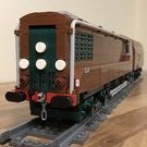
Hod Carrier Posted January 29, 2021 I know it looks like a diesel, but I promise you that it's not. This is Córas Iompair Éireann (CIE) CC1 "Turf Burner". It was a prototype 0-6-6-0T steam locomotive that was designed and built at the Inchicore Works under the directorship of O.V.S. Bulleid. As Ireland has no reserves of suitable coal, Irish railways have always been reliant on imports of Welsh steam coal. However, at times the supply of this fuel has been interrupted, such as during the two world wars. As a consequence, Irish railways have had to be inventive during times of shortage and had already carried out limited experiments on using turf or peat, which Ireland has in abundance, as a locomotive fuel. The use of turf as a fuel more generally saw a huge increase from the 1930s onwards as a means of ensuring energy security, with turf being burned in everything from electrical power stations to domestic hearths. At this point O.V.S. Bulleid joined CIE as Chief Mechanical Engineer having already acted as a consulting engineer on the Milne Report which recommended the rationalisation of the Irish railways locomotive fleet and the creation of a standard class of loco. Following trials with a converted conventional locomotive, plans were laid down for what would become CC1 which would use turf as it's primary fuel. The resulting loco was not terribly attractive and had been likened to two tenders backed up to each other. It had a central boiler with a square cross-section, a water tank at one end and a turf bunker at the other with the cabs sandwiched between. Technically, CC1 shared some features with Bulleid's earlier 0-6-6-0T, the Leader class built for Britain's Southern Railway, most notably the drive arrangements on the bogies. Like the Leader, CC1 used enclosed chains running in oil baths. Testing commenced in 1957 and CC1 was observed to have good steaming characteristics and rode quite well for a large loco. She was returned to Inchicore for modifications including spark arrestors and smoke deflectors and a nice coat of green paint together with white lining and chevrons (CC1 had previously been dark grey), although some issues remained. Judging from photos, another aspect CC1 shared with her English cousin was issues surrounding crew comfort. The cabs must have been hot because every photo I have found shows her with the doors and windows wide open, so I have modeled her in this condition. The test program continued until the end of 1958 when the project was halted following Bulleid's retirement earlier in the year. CC1 was retained at Inchicore until 1965 when she was broken up. The boiler was retained for stationary use and the frames and bogies survived into the mid-1970s. My model is of CC1 in her final configuration. Again, there are probably no particularly interesting building techniques employed except perhaps for the placement of the motors. The vertical orientation of the L-Motors leaves no room inside the body for any gearing, so the 20T bevel gear has had to go into the bogie instead which has necessitated making room for it (if you know what I mean). Due to the retirement of Power Functions, this is probably my last PF model. All future builds will have to use Powered Up. Share this post Link to post Share on other sites
CDM Posted January 29, 2021 I wasn't familiar with this locomotive and had to look it up but, wow, you nailed it. The access ladder is a bit large at the front but otherwise this is a stunning rendition of a very unique looking engine. I love it. Share this post Link to post Share on other sites
zephyr1934 Posted January 29, 2021 Your other recent build of something that looks like steam but isn't is a nice complement to something that is steam but doesn't look it. The sand green looks great and the build is impressive (even if you don't use any special techniques). Share this post Link to post Share on other sites
Hod Carrier Posted January 29, 2021 (edited) Thanks guys. She's certainly an unusual loco and a total one-off. As far as I'm aware there were no other purpose-built turf burning locos. @CDM Yes, I'd have liked a smaller and more delicate looking ladder for the front end but nothing suitable was available. @zephyr1934 I had to build her in this livery as dark grey just wouldn't have looked as good. I was lucky that the parts were available. Edited January 29, 2021 by Hod Carrier Share this post Link to post Share on other sites
bogieman Posted January 29, 2021 Such a unique locomotive. Thanks for the background info. You've made a beautiful MOC. Share this post Link to post Share on other sites
Hod Carrier Posted January 29, 2021 @bogieman Thank you so much. I always find that I get myself immersed in the detail of the models I build and end up learning a whole load more about them than is necessary to build them. I think that's why I've just built two alternative fuel locomotives rather than examples from a fleet, because I find their stories more engrossing. Share this post Link to post Share on other sites
Andy Glascott Posted January 29, 2021 This is excellent @Hod Carrier. As an Irishman, seeing CIE in the post title immediately conjured up images of black and orange, but no, you created a wonderful model of this unique beast. I’d only ever read one or two article on it, and seen a few black and white photos, but this really brings it to life. Thank you for sharing it, it’s not that often we see locos on here from my old home turf. Ahem. Share this post Link to post Share on other sites
Hod Carrier Posted January 30, 2021 @Andy Glascott Thank you. I'm happy to have been able to bring a little of the green of home to the forum. She was a pleasure to build and I'm glad to have been able to bring her to a wider audience. Share this post Link to post Share on other sites
Pdaitabird Posted January 30, 2021 That's an excellent rendition of quite an unusual locomotive! The sand green livery looks really nice. Share this post Link to post Share on other sites
Duq Posted January 30, 2021 ^ What Andy said ;-) If we get this covid thing under control we should have our second Brick Feile event in 2022. Would be great if you could join us for that. Share this post Link to post Share on other sites
LEGO Train 12 Volts Posted January 30, 2021 I did not know this very particular locomotive. Good MOC! Share this post Link to post Share on other sites
zephyr1934 Posted January 30, 2021 22 hours ago, Hod Carrier said: Yes, I'd have liked a smaller and more delicate looking ladder for the front end but nothing suitable was available. Okay, now you've got me digging, I found a photo of the nose... actually maybe that's the rear...? (you really nailed those unusual smoke deflectors and the subtle asymmetry of the prototype) It is all a matter of individual design, but did you try it without the ladder too? Another idea would be to do a ladder out of jumper plates and door rails, Or use the bottom of hinge bricks, Share this post Link to post Share on other sites
Hod Carrier Posted January 30, 2021 Thank you everyone for the amazing feedback. 1 hour ago, Duq said: If we get this covid thing under control we should have our second Brick Feile event in 2022. Would be great if you could join us for that. Wow!! That would be great. I'd love to. 59 minutes ago, zephyr1934 said: I found a photo of the nose... actually maybe that's the rear...? Yes, that's the front. Oh wait, hang on. Er... No, the rear. Probably. It is funny you should say that because there was something I forgot to mention. All the images I have found online for this loco seem to show the same side, so I've had to assume that the other side is a mirror image. Like the moon, CC1 has always hidden her "dark side". If anyone knows whether this assumption is incorrect I shall be happy to hear and to make the necessary corrections. The ladder piece is definitely horrible and I'd rather not have to use it at all. The problem is that it's right on the very front of the loco (Or is it? See above), and therefore a fairly prominent feature which I couldn't really delete. The techniques you've shown are certainly much better, but sadly won't work on this build due to the shape and construction of the front. However, I'm interested to know what that part is you've used as a ladder ahead of the bogie on the tender of your S2, as that looks just the job. Share this post Link to post Share on other sites
Brickwolf Posted January 30, 2021 Exotic prototype but instantly recognizable, great work! Share this post Link to post Share on other sites
zephyr1934 Posted January 31, 2021 22 hours ago, Hod Carrier said: Yes, that's the front. Oh wait, hang on. Er... No, the rear. Probably. It is funny you should say that because there was something I forgot to mention. All the images I have found online for this loco seem to show the same side, so I've had to assume that the other side is a mirror image. Like the moon, CC1 has always hidden her "dark side". If anyone knows whether this assumption is incorrect I shall be happy to hear and to make the necessary corrections. It is clearly designed to run comfortably either direction. The thing that threw me off is that the end you show looks like it is "tender-ish", with the foot cuts in the side. Digging more (here, here, here, and an interesting top view of a model here (finding a top view of a rare loco is always the hardest part)), it sounds like it had turf bunkers and tanks "at either end" suggesting both ends were tender-ish. Here's a view from the other end: 22 hours ago, Hod Carrier said: The ladder piece is definitely horrible and I'd rather not have to use it at all. The problem is that it's right on the very front of the loco (Or is it? See above), and therefore a fairly prominent feature which I couldn't really delete. The techniques you've shown are certainly much better, but sadly won't work on this build due to the shape and construction of the front. However, I'm interested to know what that part is you've used as a ladder ahead of the bogie on the tender of your S2, as that looks just the job. I still think it would be worth seeing how it looks without the ladder. Yes, it is front and center, but if you can't get close to scale inclusion can be as bad as exclusion. Why not pop it off for a second and see what you think? It might look completely wrong without the ladder or it might look a bit better. As for the S2, I forgot that there are two different ladders in that image. I was trying to highlight the bottom side of the sand green hinge brick on the boiler, but the black ladder on the tender is from this family of ladders, Share this post Link to post Share on other sites
Hod Carrier Posted January 31, 2021 1 hour ago, zephyr1934 said: It is clearly designed to run comfortably either direction. Yes, definitely. In common with the Leader class, CC1 was designed to have the same flexibility of operation as would be afforded by a conventional tank engine or a double-ended diesel. As such, terms like "front" and "back" are meaningless. In normal railway parlance, you would refer to either #1 or #2 end (or perhaps A or B). 1 hour ago, zephyr1934 said: The thing that threw me off is that the end you show looks like it is "tender-ish", with the foot cuts in the side. Digging more (here, here, here, and an interesting top view of a model here (finding a top view of a rare loco is always the hardest part)), it sounds like it had turf bunkers and tanks "at either end" suggesting both ends were tender-ish. Here's a view from the other end: During my research I was able to dig up a technical cutaway of CC1 in a German language publication that showed the internal layout (follow the link and scroll up a bit). This indicated that the water tank and turf bunker were at opposite ends of the loco. The inset steps on the side are, as far as I can discern, at the water tank end. The images you've linked to represent most of the sources I had available to use. By referencing the differences caused by the asymmetry of the loco you can see that, although you can see both ends, you only ever see one side. The image of the roof is only of a model though, so I've had to treat it with caution. I have included centrally positioned safety valves and vents for the blowers at each end based on the cutaway referred to above, and the two chimneys by reference to images of the loco in steam. However, it's all still best guess as clearly there must be some other features up there, such as a means of accessing the turf bunker to facilitate fueling. I shall be seeking further clarification on both of these matters. 1 hour ago, zephyr1934 said: I still think it would be worth seeing how it looks without the ladder. Yes, it is front and center, but if you can't get close to scale inclusion can be as bad as exclusion. Why not pop it off for a second and see what you think? It might look completely wrong without the ladder or it might look a bit better. As for the S2, I forgot that there are two different ladders in that image. I was trying to highlight the bottom side of the sand green hinge brick on the boiler, but the black ladder on the tender is from this family of ladders, I do get your point and I know exactly what you mean. Modelling in LEGO is a balancing act between what looks right and what is achievable, and regrettably the need to make this ladder part suitable for those wretched Minifigs does mean that it ends up massively out-of-scale in this instance. However, I do prefer the look of your custom alternative and am likely to be in touch with an order in due course. Share this post Link to post Share on other sites
Paperinik77pk Posted February 1, 2021 Great locomotive - very...unusual!!! I like it a lot!!! Yes, the ladder is a bit big, but the "feeling" of the locomotive is there. It "feels" a simple locomotive to be reproduced, but in reality, looking at the pictures...it's a mess (at least for me). And as usual you got all the details! What a strange beast - I NEED to know more about it! Ciao Hod! Davide Share this post Link to post Share on other sites
zephyr1934 Posted February 1, 2021 22 hours ago, Hod Carrier said: and regrettably the need to make this ladder part suitable for those wretched Minifigs You are simply too kind to your minifigs. You keep this up and they will start asking for weekends and holidays off too (grin) 21 hours ago, Hod Carrier said: During my research I was able to dig up a technical cutaway of CC1 in a German language publication that showed the internal layout (follow the link and scroll up a bit). This indicated that the water tank and turf bunker were at opposite ends of the loco. The inset steps on the side are, as far as I can discern, at the water tank end. You are dragging me down the rabbit hole. The more I look the crazier the loco becomes. Looking at the cross section schematic in the German book and comparing it to both the photos and the external schematic on this UK page I referenced earlier, it appears that the "cutouts" are for water tank filling (#15 on the German schematic), which suggests to me that there are tanks on both ends. I am starting to suspect that the horizontal series of rectangular indentations on the lower right end of the locomotive is on the right end of either side when the viewer is facing the locomotive (hence, all the photos you've found appear to be the same side, because the sides are asymmetrical in the same way on either side). These rectangular indentations might correspond to #11 in the German schematic (a pre-heater?) but if so, it is on the the wrong end in the schematic (left instead of the right, but maybe the graphic designer flipped the image before adding the labels? I've seen other images flipped in reputable books before). Whatever those rectangles are on the right end, it would preclude the side steps to reach the tank lid above. But it would make sense if there was a single tank on either end of the engine with access lids on either side and perhaps even having the tanks on both ends connected by a pipe so that one only needs to fill the tanks from one location and thus, only one set of side steps (on the left) and the tank lid on the right only there for backup, ventilation, and servicing. It would also make sense to have the top of the water tanks only half way up to keep the center of gravity lower, in which case, having the fuel above the water tank would also make sense. The images on the UK page show the rectangular hatches on the roof, 3 on each end on each side. While the German schematic appears to show the interior of three turf bunkers on the right and exterior doors of three bunkers on the left. Share this post Link to post Share on other sites
Hod Carrier Posted February 1, 2021 8 hours ago, Paperinik77pk said: Great locomotive - very...unusual!!! I like it a lot!!! Yes, the ladder is a bit big, but the "feeling" of the locomotive is there. It "feels" a simple locomotive to be reproduced, but in reality, looking at the pictures...it's a mess (at least for me). And as usual you got all the details! What a strange beast - I NEED to know more about it! Thank you, Davide. Yes she's a it of a mess, but then she was designed for practicality rather than aesthetics. The history that I have provided at the top of this thread is really just a basic summary, but it covers most of the important details. More information about her can be found in various places online, such as the Bulleid locos website. 7 hours ago, zephyr1934 said: You are simply too kind to your minifigs. You keep this up and they will start asking for weekends and holidays off too (grin) They should consider themselves lucky I haven't provided them with a fireman's pole, suitably greased of course. 7 hours ago, zephyr1934 said: You are dragging me down the rabbit hole. The more I look the crazier the loco becomes. Looking at the cross section schematic in the German book and comparing it to both the photos and the external schematic on this UK page I referenced earlier, it appears that the "cutouts" are for water tank filling (#15 on the German schematic), which suggests to me that there are tanks on both ends. I am starting to suspect that the horizontal series of rectangular indentations on the lower right end of the locomotive is on the right end of either side when the viewer is facing the locomotive (hence, all the photos you've found appear to be the same side, because the sides are asymmetrical in the same way on either side). These rectangular indentations might correspond to #11 in the German schematic (a pre-heater?) but if so, it is on the the wrong end in the schematic (left instead of the right, but maybe the graphic designer flipped the image before adding the labels? I've seen other images flipped in reputable books before). Whatever those rectangles are on the right end, it would preclude the side steps to reach the tank lid above. But it would make sense if there was a single tank on either end of the engine with access lids on either side and perhaps even having the tanks on both ends connected by a pipe so that one only needs to fill the tanks from one location and thus, only one set of side steps (on the left) and the tank lid on the right only there for backup, ventilation, and servicing. It would also make sense to have the top of the water tanks only half way up to keep the center of gravity lower, in which case, having the fuel above the water tank would also make sense. The images on the UK page show the rectangular hatches on the roof, 3 on each end on each side. While the German schematic appears to show the interior of three turf bunkers on the right and exterior doors of three bunkers on the left. Ha ha!! I've got you properly hooked now. It's funny, but the more I search the more confusing it gets. I have found sources saying that the water tanks and turf bunkers were at opposite ends and others saying that they were at both ends as you describe, a bit like a Fairlie but with just one boiler. The problem now is that there is nothing left of the loco to point to to get a definitive answer. Dividing the fuel and water storage between the ends complicates matters as it requires replication of technical features, such as the augers for feeding the boiler with turf, and complicates fueling and watering, but that doesn't mean that it wasn't so. The history that I have presented up-thread is intended to be an introduction only and has been drawn from a number of online sources, the accuracy of which I cannot vouch for. I think that the technical cutaway is correct, as it appears to be a reproduction of a technical drawing shown in this thread on the Irish Railway Modeller forum. Sadly the images posted there are not very distinct but enough can be ascertained to verify that they are the same drawings. Share this post Link to post Share on other sites
zephyr1934 Posted February 2, 2021 Congratulations! You have just won the "most baffling locomotive" award for this month. (grin) Share this post Link to post Share on other sites
Hod Carrier Posted February 2, 2021 If only that was a category in the Brick Train Awards. Share this post Link to post Share on other sites
Hod Carrier Posted April 8, 2021 On 2/1/2021 at 3:42 PM, zephyr1934 said: You are dragging me down the rabbit hole. The more I look the crazier the loco becomes. Looking at the cross section schematic in the German book and comparing it to both the photos and the external schematic on this UK page I referenced earlier, it appears that the "cutouts" are for water tank filling (#15 on the German schematic), which suggests to me that there are tanks on both ends. I am starting to suspect that the horizontal series of rectangular indentations on the lower right end of the locomotive is on the right end of either side when the viewer is facing the locomotive (hence, all the photos you've found appear to be the same side, because the sides are asymmetrical in the same way on either side). These rectangular indentations might correspond to #11 in the German schematic (a pre-heater?) but if so, it is on the the wrong end in the schematic (left instead of the right, but maybe the graphic designer flipped the image before adding the labels? I've seen other images flipped in reputable books before). Whatever those rectangles are on the right end, it would preclude the side steps to reach the tank lid above. But it would make sense if there was a single tank on either end of the engine with access lids on either side and perhaps even having the tanks on both ends connected by a pipe so that one only needs to fill the tanks from one location and thus, only one set of side steps (on the left) and the tank lid on the right only there for backup, ventilation, and servicing. It would also make sense to have the top of the water tanks only half way up to keep the center of gravity lower, in which case, having the fuel above the water tank would also make sense. The images on the UK page show the rectangular hatches on the roof, 3 on each end on each side. While the German schematic appears to show the interior of three turf bunkers on the right and exterior doors of three bunkers on the left. Just a quick bump to confirm that you were correct in your assertion. With the help of those wonderfully helpful chaps over on the Irish Railway Modeller forum I've been able to clarify the layout of CC1 and to correct my model accordingly. The "handed" nature of the design tricked me into thinking that I'd not seen both sides of the loco when in fact I had and, with their help, I've worked out how to identify which side was which. They also very generously shared images of the roof which I had not previously seen. Here's the corrected CC1 in a couple of fictional liveries. Share this post Link to post Share on other sites
zephyr1934 Posted April 8, 2021 2 hours ago, Hod Carrier said: With the help of those wonderfully helpful chaps over on the Irish Railway Modeller forum I've been able to clarify the layout of CC1 and to correct my model accordingly. The "handed" nature of the design tricked me into thinking that I'd not seen both sides of the loco when in fact I had and, with their help, I've worked out how to identify which side was which. They also very generously shared images of the roof which I had not previously seen. Here's the corrected CC1 in a couple of fictional liveries. That is most excellent all the way around! The locomotive looks great Share this post Link to post Share on other sites
Commander Wolf Posted April 9, 2021 The marginally less unsuccessful Leader 2.0! I didn't see any pic/comment about it: what did you do for the third axle in the bogies? Is it sliding? How did you route the gearing around it? Share this post Link to post Share on other sites
Hod Carrier Posted April 11, 2021 (edited) On 4/9/2021 at 9:25 PM, Commander Wolf said: The marginally less unsuccessful Leader 2.0! Only marginally. On 4/9/2021 at 9:25 PM, Commander Wolf said: The marginally less unsuccessful Leader 2.0! I didn't see any pic/comment about it: what did you do for the third axle in the bogies? Is it sliding? How did you route the gearing around it? The middle axle is a dummy, following the example from @dtomsen's DSB Litra MZ I. Dennis used hockey pucks as blind drivers mounted on non-friction axle pins, but these are rare and expensive parts in the UK so I used 2x2 round plate with a cross hole and a 2x2 round tile with an open stud and mounted them on 2L axles to allow free rotation instead. It has the advantage that you can have a central bogie pivot and not have to worry about routing the drivetrain around a central axle. Here is Dennis's technique. DSB Litra MZ I (8-wide) by Dennis Tomsen, on Flickr Edited April 11, 2021 by Hod Carrier Share this post Link to post Share on other sites