Recommended Posts

After @Marxpek 's cool post about the Ripsaw EV1, and seeing the EV3 from the same autor (https://www.renderhub.com/dmitriykotliar/ripsaw-ssr1-ev3), I decided to try to do it. Although not anywhere as extreme, "only" using 2 L-motors.
Yesterday I made an early prototype and I think it turned out alright. I still have to fix some colors when I get the parts, and figure out how to do a proper tail wing. 

I'm using the smaller sprocket wheels and I was wondering, is there an advantage to using bigger ones? They'd give more speed, but that can be achieved though gearing also.


IMG_0287.JPGIMG_0288.JPGIMG_0289.JPGIMG_0290.JPG

Edited by ozacek

Share this post


Link to post
Share on other sites
8 hours ago, ozacek said:

After @Marxpek 's cool post about the Ripsaw EV1, and seeing the EV3 from the same autor (https://www.renderhub.com/dmitriykotliar/ripsaw-ssr1-ev3), I decided to try to do it. Although not anywhere as extreme, "only" using 2 L-motors.
Yesterday I made an early prototype and I think it turned out alright. I still have to fix some colors when I get the parts, and figure out how to do a proper tail wing.

Nice look! Also great you're using PF equipment. Say, do you use a subtractor or does each motor drive one track alone? Hope you'll provide instructions.

8 hours ago, ozacek said:

I'm using the smaller sprocket wheels and I was wondering, is there an advantage to using bigger ones? They'd give more speed, but that can be achieved though gearing also.

I'm not an expert, but bigger sprocket wheels allow for a bigger radius which I think makes the tracks run easier around the drive wheels.

From what I experienced on my first tracked vehicle - though using the old tracks - I also think your tracks look too tight - unless this is due to all the supports. The problem is, one additional track part will usually have a (too) big effect, alternatively you could move the front wheel and support one stud back. But you should still try if it makes a difference, when your vehicle is ready to drive. For mine I saw a considerable difference between tight tracks and not so tight tracks on carpet.

Share this post


Link to post
Share on other sites
4 hours ago, johnnym said:

Nice look!Also great you're using PF equipment. Say, do you use a subtractor or does each motor drive one track alone? Hope you'll provide instructions.

I put too much money into PF components to switch to another system.. plus I don't have a smartphone, so Control+ is a definite no-go for me. 

I do use a substractor, but still driving each track with its own motor. The reason I have the substractor is to power the fake V6 that lies underneath, and to guarantee equal speed on both sides (slight variations will make the direction drift). I didn't want to power the tracks with the combined motors because then it's double the torque on a single path.

I'll most likely make instructions, though I'm using two non-Lego curved 5 x 3 panels in the frame, which will be a problem.

4 hours ago, johnnym said:

I'm not an expert, but bigger sprocket wheels allow for a bigger radius which I think makes the tracks run easier around the drive wheels.

From what I experienced on my first tracked vehicle - though using the old tracks - I also think your tracks look too tight - unless this is due to all the supports. The problem is, one additional track part will usually have a (too) big effect, alternatively you could move the front wheel and support one stud back. But you should still try if it makes a difference, when your vehicle is ready to drive. For mine I saw a considerable difference between tight tracks and not so tight tracks on carpet.

I guess I'll modify it to use the bigger sprockets then. 

The tracks are tight indeed, but I thought it didn't matter, thanks for pointing that out. The reason why I removed one track is because it looked very loose otherwise. I'll try the one-stud offset, or maybe when I change the sprocket size the problem will sort itself.

Share this post


Link to post
Share on other sites

I came back to this project and made some progress. I raised the motors to be more prominent, fine-tuned the cabin, Improved the stability of the top cover, switched to large sprocket wheels, and fixed all the half-stud alignments (there are quite a few).

However I still have trouble with feeding the power to the wheels, since I'm using U-joints and the angles are now too big. Starting by rerouting the axles down currently leads to too much vibration, and heaving gear clicking. Still thinking...

And BTW, I previously mixed up terminology: I'm not using a substractor but simple hard-coupling. First there's very limited space at the back, and also one would typically use two motors of different size (which I can't do here obviously).

IMG_0350.JPG

IMG_0351.JPG

Edited by ozacek

Share this post


Link to post
Share on other sites
5 hours ago, ozacek said:

I came back to this project and made some progress. I raised the motors to be more prominent, fine-tuned the cabin, Improved the stability of the top cover, switched to large sprocket wheels, and fixed all the half-stud alignments (there are quite a few).

However I still have trouble with feeding the power to the wheels, since I'm using U-joints and the angles are now too big. Starting by rerouting the axles down currently leads to too much vibration, and heaving gear clicking. Still thinking...

Why not moving the PF L motors behind the battery box and the fake motor up. I can't say for sure, but maybe there's enough room to connect them to the sprocket wheels with a single 90° angle avoiding the U-joints.

Or you could use the same method as in the 42095 A model.

5 hours ago, ozacek said:

And BTW, I previously mixed up terminology: I'm not using a substractor but simple hard-coupling. First there's very limited space at the back, and also one would typically use two motors of different size (which I can't do here obviously).

But when you hard-couple both PF L motors, how can you steer the vehicle?

Share this post


Link to post
Share on other sites
1 hour ago, johnnym said:

Why not moving the PF L motors behind the battery box and the fake motor up. I can't say for sure, but maybe there's enough room to connect them to the sprocket wheels with a single 90° angle avoiding the U-joints.

Of course I could do that, but the original vehicle has the motors way up, and I like that look :)


1 hour ago, johnnym said:

But when you hard-couple both PF L motors, how can you steer the vehicle?

Good point... hadn't thought of that :D   I guess I would have found out right at the end :)

I only got into technic two years ago, and this is only the 2nd time I'm designing something from scratch, so I do still make that kind of mistakes...

Share this post


Link to post
Share on other sites
21 hours ago, ozacek said:

Of course I could do that, but the original vehicle has the motors way up, and I like that look :)

You're right, it really looks good that way. But when you move the fake engine up, you'd also have an engine there. And you could use bricks to detail it even more than the two PF L motors would allow.

Other idea: Why not use the U-joints first - BTW, are CV-joints out of the question? - and make the 90° direction change (not down but to the left and to the right) directly near the sprocket wheels? I think this would also save you two gears per track.

21 hours ago, ozacek said:

I only got into technic two years ago, and this is only the 2nd time I'm designing something from scratch, so I do still make that kind of mistakes...

You would be wondering how often I - of course only after building :blush: - notice a mechanism's non-functionality. But to my defense, I only started this technic building in February or so. :wink:

Share this post


Link to post
Share on other sites
2 hours ago, johnnym said:

You're right, it really looks good that way. But when you move the fake engine up, you'd also have an engine there. And you could use bricks to detail it even more than the two PF L motors would allow.

I still prefer the look of the two L-motors standing up there... (but I might change my mind if it prooves too hard or too weak).
 

2 hours ago, johnnym said:

Other idea: Why not use the U-joints first - BTW, are CV-joints out of the question? - and make the 90° direction change (not down but to the left and to the right) directly near the sprocket wheels? I think this would also save you two gears per track.

I'm not sure I fully understand your suggestion... maybe I need a drawing :)
(If you're talking about directly linking the motors' output with the wheels, that's what I first tried, but the angles are too big for the joints).

Edited by ozacek

Share this post


Link to post
Share on other sites

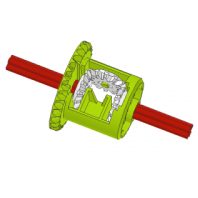
Actually I think I found a solution that solves all problems: it keeps the motors up, the U-joints angles below 45, removes the hard-coupling but still allows to drive the fake engine (via a differential).

Ripsaw+drivetrain.png

Share this post


Link to post
Share on other sites

I finished the design, and I will now go on with the tedious task of making instructions for it.  I'm happy that I could keep the build very modular - all these modules more or less just clip to each other:

IMG_0366.JPG

Share this post


Link to post
Share on other sites
On 10/21/2019 at 2:19 AM, ozacek said:

Actually I think I found a solution that solves all problems: it keeps the motors up, the U-joints angles below 45, removes the hard-coupling but still allows to drive the fake engine (via a differential).

Ripsaw+drivetrain.png

Sorry, I was away for a few days. But this is more or less, what I had in mind. Except that I assumed the black parts close to the sprocket wheels could be used rotated 90°, but obviously the height difference is too big to do that.

Congrats on this machine! :sweet: I'd really like to see it in action. From what I see here:

...I should have everything, except for the dozens of bevel gears with pin hole, but maybe pulley wheels could also work there instead.

Share this post


Link to post
Share on other sites
4 hours ago, johnnym said:

...I should have everything, except for the dozens of bevel gears with pin hole, but maybe pulley wheels could also work there instead.

Probably, since Lego alternatively uses both in their tracked models.
Note that you actually need 6 soft-spring shocks, not hard-spring ones like on the prototype. With 6 hard shocks on such a mid-size machine, you could as well use beams :)

IMG_0376.JPG

Share this post


Link to post
Share on other sites

It turns out the traction doesn't work after all, the powering axles invariably pop out of their socket after a few seconds. It looks like I can't use small 12T bevel gears after... some serious redesign will be needed.

Share this post


Link to post
Share on other sites
5 hours ago, ozacek said:

It turns out the traction doesn't work after all, the powering axles invariably pop out of their socket after a few seconds.

Using a 3L axles with stop instead doesn't help? In order to make enough room for the stop, It could be necessary to change the 3L axle connectors near the sprocket wheels for 2L ones and use a +1L longer axle to connect to them. But maybe then the U-joints pop out instead...

Share this post


Link to post
Share on other sites
6 hours ago, johnnym said:

Using a 3L axles with stop instead doesn't help? 

That's a simple solution I didn't think about! However I already redesigned it, and it's actually much better, everything around the moving parts now holds much stronger.

EDIT:
ah but wait, there's a reason I didn't think about that: you can' insert a 3L axle pin stop with the stop inside the black axle holder part..

Edited by ozacek

Share this post


Link to post
Share on other sites

This time it's complete, tested & working. Instructions are ~80% complete.

IMG_0384.JPG
IMG_0386.JPG
IMG_0389.JPG
IMG_0387.JPG

Edited by ozacek

Share this post


Link to post
Share on other sites

Does it look better with black tracks? I find the front part does, but then the rear is black-over-black...

IMG_0390.JPG

Share this post


Link to post
Share on other sites
On 10/27/2019 at 1:53 PM, ozacek said:

That's a simple solution I didn't think about! However I already redesigned it, and it's actually much better, everything around the moving parts now holds much stronger.

EDIT:
ah but wait, there's a reason I didn't think about that: you can' insert a 3L axle pin stop with the stop inside the black axle holder part..

Ok, I thought if it doesn't break it would be allowed :wink: It's some fiddling, but it "works".

But still better that you found an alternative to bending parts.

19 hours ago, ozacek said:

This time it's complete, tested & working. Instructions are ~80% complete.

Nice one, especially the side profile of the tracks - it captures the look of the real tracks very well I think.

12 hours ago, ozacek said:

Does it look better with black tracks? I find the front part does, but then the rear is black-over-black...

Well, I can't really tell. The gray tracks add a little more contrast to it. The black tracks might be closer to reality. Ever tried black and gray alternating? Might look strange, but I could imagine that it will create some interesting effect when driving. :classic:

Share this post


Link to post
Share on other sites
5 hours ago, johnnym said:

Ok, I thought if it doesn't break it would be allowed :wink: It's some fiddling, but it "works".

Ohh I see what you mean. No, I don't do that :)  If there's something I learned by designing Technics, it's that there's always a solution, no matter how hard it looks.

5 hours ago, johnnym said:

Ever tried black and gray alternating? Might look strange, but I could imagine that it will create some interesting effect when driving. :classic:

Exactly my thinking :)  I tried that yesterday, it looks good, but I still can't quite make up my mind. What do you think?  @others: an opinion maybe?

IMG_0394.JPG

For comparision:

Ripsaw+Comparision.jpg

Edited by ozacek

Share this post


Link to post
Share on other sites
3 minutes ago, ozacek said:

Ohh I see what you mean. No, I don't do that :)  If there's something I learned by designing Technics, it's that there's always a solution, no matter how hard it looks.

You're right, but I'm more of a "do it right later if it works good enough now" guy. :wink: There comes a problem with that: most of my models are WIP constantly.

3 minutes ago, ozacek said:

Exactly my thinking :)  I tried that yesterday, it's nice, and I'm tempted to go with that, but I still can't quite make up my mind. What do you think?

It reminds me of something, but I can't say what...

....or wait, yeah, the Cheshire Cat from Alice's Adventures in Wonderland :laugh:

It looks interesting and different - I'd keep it for the uniqueness alone. And looking back at the other two versions, I'd stay with this one, it's more attractive.

Share this post


Link to post
Share on other sites
21 minutes ago, andythenorth said:

The angle on the u-joints near the sprockets looks brutal, but does it run well? :classic: :thumbup:

You're right, it is very near the limit, and because of that their rotation isn't completely smooth. But there's no effect I can see when the vehicle runs (although power is most likely lost because of that).
When you let in run in the air, you can feel it's a bit 'stacato'. It reminds a bit of the bursts of combustion engine pistsons - it's actually not a bad effect :)

Share this post


Link to post
Share on other sites
3 hours ago, johnnym said:

....or wait, yeah, the Cheshire Cat from Alice's Adventures in Wonderland :laugh:

:D   How about that:

Ripsaw+Chestershire.jpg

Edited by ozacek

Share this post


Link to post
Share on other sites

Create an account or sign in to comment

You need to be a member in order to leave a comment

Create an account

Sign up for a new account in our community. It's easy!

Register a new account

Sign in

Already have an account? Sign in here.

Sign In Now

  • Recently Browsing   0 members

    No registered users viewing this page.