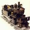
Srbandrews Posted December 17, 2014 (edited) Well this is my first attempt at a proper train MOC and by far the biggest MOC I've made to date, so go easy on me. Apologies for the crummy photos - phone camera only available. UPDATE: Recent Image I had to make a few compromises and fudges with scale to try to find a rough marriage between the right scale compared with the driver wheels, the gauge and an approximate minifig scale. Quite a few things not quite finished but I'm pretty happy with how it's turned out. In future I might move the cylinders onto the boiler plate and try to get it working, but I'm not sure there would be enough play in the bogey to round a corner. Edited January 2, 2015 by Srbandrews Share this post Link to post Share on other sites
Zerobricks Posted December 17, 2014 Looks good. Will you motorize it? Share this post Link to post Share on other sites
Srbandrews Posted December 17, 2014 Oh, I just have a motorized boxcar that I made for the Lone Range Constitution train that I use to run it around my little oval of track. I could fit the workings of that into the tender without much modification though, I'm just not quite ready to buy a whole new PF set. Share this post Link to post Share on other sites
Redimus Posted December 17, 2014 (edited) I think that overall you've managed to capture a good likeness, especially for a first loco MOC. I've some suggestions for the tender; Firstly, I think it's a little short, both in length and (to a lesser extent) height. (Making it bigger would also help should you chose to to put the PF stuff in the the tender.) Secondly the back of the tender really should be green too. Thirdly (and finally), have you tried using 1x2 jumper plates for the steps on the back, it'd make them closer to the prototype (see image). Here's how I did it for my 7 wide Southern Railway Q Class. At 6 wide, you'll either have to have offset steps, but only on one side, or steps on both sides, but one directly above the other. (Also, ignore the wonky buffers I keep forgetting to fix on the LDD, lol) Edited December 17, 2014 by Redimus Share this post Link to post Share on other sites
garethjellis Posted December 18, 2014 (edited) You did a great job, the thing you will soon learn, even when you think you have finished you will see something else you will want to change. Thats the beauty of Lego right?!? Edited December 18, 2014 by garethjellis Share this post Link to post Share on other sites
jtlan Posted December 18, 2014 Welcome to the world of train MOCs, @Srbandrews! You've done a good job of capturing the stepped/sloped look of the boiler. I would recommend using slope bricks instead of bowed ones for the main part of the boiler, to better distinguish the roundness of the boiler from the part above the firebox. You might also consider switching to Big Ben Bricks XL drivers, which I think would be better suited for modeling the King Class' 78-inch drivers. Share this post Link to post Share on other sites
Redimus Posted December 18, 2014 (edited) the thing you will soon learn, even when you think you have finished you will see something else you will want to change, Oh god ain't that the truth! I don't think I have a single 'final version' LDD file that is *exactly* the same as the actual final build. Edited December 18, 2014 by Redimus Share this post Link to post Share on other sites
Dread Pirate Rob Posted December 18, 2014 Great first MOC! Great use of parts for the lamps on the buffer beam. For the piston rods there are some great examples on this forum for using various rods fixed to the piston that don't move and are not connected by connecting rods to the side rods. This fills the gap and adds detail when a connection is a mechanical impossibility. One simple example from a second rate builder is here: https://www.flickr.com/photos/128987084@N02/15061297343/ One compex example from a first rate builder is here: http://www.deviantart.com/art/French-2-4-0-Steam-Locomotive-428524646 Share this post Link to post Share on other sites
LEGO Train 12 Volts Posted December 18, 2014 Nice first work! I like the roof of the cabin with two kind of slope! Well done! Share this post Link to post Share on other sites
Srbandrews Posted December 18, 2014 (edited) Thanks for the feedback, guys. Lots to think about. Redimus: You're totally right about it being too short and the main offender is the tender. When I was building the chassis, I ended up intentionally building the tender shorter than it should be just because making it to the correct length required additional points if articulation. It's definitely something I'll look at changing in the future. I will definitely change the back of the tender - I don't think I have enough green plates to build it up the way you have but for the timebeing I can at least compromise using cheese wedges on headlight bricks. Jtlan: I agree with you about the firebox shape. Those curved-top bricks could have been made for that particular cross-section, and so it was a shame not to get a better contrast with the boiler. In the end though, it just came down to the fact that I liked how this looked better when compared with both the octagonal boiler style of using sloped bricks and the round 4x4 bricks set on their side method. Just gives a better look along the top I feel. Edited December 18, 2014 by Srbandrews Share this post Link to post Share on other sites
Redimus Posted December 18, 2014 I can at least compromise using cheese wedges on headlight bricks. Not a bad idea that. Share this post Link to post Share on other sites
Srbandrews Posted December 18, 2014 Thanks again for the tip Redimus. This is how the tender looks now - with a couple of other minor improvements. I think it looks a lot better: What I didn't mention, and something that substantially informed my design choices (especially in terms of colour and level of detail I was trying to achieve), is that my main inspiration for building this was an original BR(W) poster that my partner bought me for my birthday a couple of weeks ago. In a sense I was as much trying to model the loco in the image as I was the prototype for it. Share this post Link to post Share on other sites
LEGO Guy Bri Posted December 19, 2014 Very nice steamer Srbandrews. Those slight alterations on the tender do look much better Share this post Link to post Share on other sites
zephyr1934 Posted December 19, 2014 That is a really great build and hard to believe it is your first steam engine. It also does a good job capturing the look of the poster (of course now you have to build those coaches too... grin). In all seriousness, it looks really good. One suggestion, above the last driver wheel, did you consider using 1x2x1 curved slope in place of the cheese and tile on the leading edge? One word of warning (which you probably have already thought of), with three axles the tender might prove to be problematic in curves, especially if you increase the spacing between axles. There are various tricks you can to to make the middle axle "float" or articulated so that it will negotiate curves without problems (or just pop the axle out and keep the wheel holder to create the illusion of a third axle). Share this post Link to post Share on other sites
Redimus Posted December 19, 2014 Nice work on the tender. Keep up the good work! Share this post Link to post Share on other sites
Srbandrews Posted December 19, 2014 (edited) Thanks guys. I have to say I'm really enjoying tinkering with this build and trying to refine it bit by bit. Last night I added some details to the tender and cab interior. I also made my first attempt at 'working' rods. I didn't have any 'thin' lift arms so had to settle for some black tiles for now. Added yesterday's advent surprise General Rieekan for scale. It seems to work ok and doesn't appear to add too much friction but it does 'feel' a bit bulky, so I'm considering replacing the piston rod axle piece with a 6L bar instead. This is how it looks running: Like I said, it seems to work well but I'm just wondering if I missed anything obvious with my setup? One suggestion, above the last driver wheel, did you consider using 1x2x1 curved slope in place of the cheese and tile on the leading edge? One word of warning (which you probably have already thought of), with three axles the tender might prove to be problematic in curves, especially if you increase the spacing between axles. There are various tricks you can to to make the middle axle "float" or articulated so that it will negotiate curves without problems (or just pop the axle out and keep the wheel holder to create the illusion of a third axle). Thanks for reminding me. I did order enough parts to do that but couldn't find the curved slope pieces when it came to building it. Thankfully I've found them now so that's fixed. As for the tender wheel configuration; that's exactly the problem I encountered when I was working on getting the chassis round corners and the reason the tender is so short now. Not sure if I care enough about tenders to tackle this yet. Edited December 19, 2014 by Srbandrews Share this post Link to post Share on other sites
lightningtiger Posted December 19, 2014 AWESOME steam train there 'Srbandrews'.....I like the detailing exterior and interior (driver's cab)......Brick On 'Srbandrews' ! Share this post Link to post Share on other sites
locoworks Posted December 19, 2014 a key feature of the kings was the front bogie, it looked to have internal and external axleboxes/hornblocks, not easy to model?? Share this post Link to post Share on other sites
Srbandrews Posted December 19, 2014 a key feature of the kings was the front bogie, it looked to have internal and external axleboxes/hornblocks, not easy to model?? Oh yes, you're absolutely right. Well no, it's not at all difficult but I don't have the right kind of wheel. Thanks a lot for pointing that out. AWESOME steam train there 'Srbandrews'.....I like the detailing exterior and interior (driver's cab)......Brick On 'Srbandrews' ! Thanks! Couple more edits: I've made both the engine and the tender taller by one plate, lengthened the firebox and bogie by one stud, and raised the top of the boiler. This allowed me to get a continuous line running along through the handrail and the black stripe on the tender. I decided that, for me, the drop in the curved bricks at the dome gives enough of the tapering effect so straightened the top of the silhouette. The dip in the middle of the boiler was, I felt, making the loco look less 'powerful', and really more like the more tapered Hall class boiler. I'm pretty happy with the way the boiler looks now - seems sleeker. Share this post Link to post Share on other sites
Srbandrews Posted January 2, 2015 (edited) Sorry to bump my own thread, but I've made some further improvements to the engine which I wanted to add: A couple of things have been changed on the engine itself: The rear pair of wheels on the front bogie has been changed to better match the inside bearings on the prototype; I've switched out the gold dome for a gold fez; The rods have been changed up a bit; I've made some minor improvements to the cab interior. One quite big concession I had to make was reducing the wheelbase of the drivers. I realised that spaced out over 11 studs they were dragging quite a lot around corners and I wanted the engine to run with as little friction as possible. I experimented with changing the position of the flanged wheels but, in the end, I found that there didn't seem to be a better alternative to reducing the wheelbase to 9 studs a la the Emerald Night. I've left the wheel arches where they were with the intention of creating a slight illusion of the wheels being in the right place and the maintain the proportions of the loco. I think it looks ok and it doesn't slow down too much on corners now. The main changes, though, are on the tender: I've extended the tender considerably. The main reason for this was to add power functions but it actually makes the tender much closer to the right sort of length compared with the engine. It's not perfect, but I didn't want to go as tall as I would need to go to completely hide the battery back and IR receiver. I'm pretty happy with how it turned out and it runs beautifully now. Just need some British Railways roundel stickers and some carriages now -_- Edited January 4, 2015 by Srbandrews Share this post Link to post Share on other sites
MusicaRibelle Posted January 2, 2015 Well done! It's actually very nice and instructive to see the progress of your project over time. It looks really good now, and it runs really well. Looking forward to seeing this thread bumped again with pictures of a passenger car or two attached to the beautiful engine ;) Share this post Link to post Share on other sites
Srbandrews Posted January 2, 2015 Well done! It's actually very nice and instructive to see the progress of your project over time. It looks really good now, and it runs really well. Looking forward to seeing this thread bumped again with pictures of a passenger car or two attached to the beautiful engine ;) Thanks! I actually recently lost my mind somewhat and bought the Emerald Night. It's on its way in the post now so when it arrives next week I will of course take some snaps of this loco with the EN passenger carriage. I've also bought some a few parts in preparation of making a second similar car when it arrives, although I wasn't prepared to shell out for the tan train windows (so expensive) so I bought standard tan 1x4x3 windows. I might make something where the windows are less of a feature like a mail car or passenger brake car. After that, I don't think the bogie motor will pull more than two without struggling a bit. Share this post Link to post Share on other sites
locoworks Posted January 2, 2015 nice improvement on the front bogie, a couple more points, the piston rod in the cylinder lines up, even if the cylinder is mounted at a slight angle with the main driven axle centre line, usually the centre axle on a 6 coupled loco. it would connect to the same crank pin as the coupling rod journal the piston rod lines up with. it connects centrally so the deflection angles are the same +/- . I cant recall a connecting rod ever attaching to a coupling rod between journals except perhaps jackshaft drives? Share this post Link to post Share on other sites
Srbandrews Posted January 2, 2015 Thanks locoworks. In this case, I was aware of that as an issue. Unfortunately, given how tight lego corners are, the front bogie needs a much greater arc of movement than it would do in the prototype. That really limits where you can place the cylinder, so I had to move it both above and behind its correct position so as not to block the bogie. Because the cylinders are so high up, the wheel motion doesn't convert so well between the angles of the rods and often exerts a turning force on the 'piston', jamming the whole gear. To reduce this, I found that the best remedy was to use the longest possible rod (in the case a 7l thin liftarm) to reduce the angles, though this meant connecting it further away from the cylinders. With the setup as it is, I have very little friction and the gear never jams, though I admit it's not ideal for accuracy. Share this post Link to post Share on other sites
locoworks Posted January 3, 2015 I realise there are some things you just cant do with lego and what you have done is very good. could you cheat and widen the cylinders to get clearance? and then use two bits to make a stepped connecting rod? it would only give you 1 stud extra clearance either side but it may work?? maybe another option is redesign the front bogie so nothing that moves laterally is higher than the wheel flanges? would gain more space further forward for stuff? Share this post Link to post Share on other sites