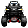
JM1971 Posted September 15, 2013 Posted September 15, 2013 (edited) Features: 4WD Independent Suspension Steering Servo 2 XL Motors http://www.brickshelf.com/gallery/JM1971/LDD/rage-buggy.lxf Edited October 19, 2013 by JM1971 Quote
TasV Posted September 15, 2013 Posted September 15, 2013 Is there a new version of LDD out that can make these renders or did you do them from screen shots in something like Photoshop? I don't think my LDD (V 4.3) can do such lovely renders. Quote
JM1971 Posted September 15, 2013 Author Posted September 15, 2013 LDD2POVray... http://ldd2povray.lddtools.com/ Fairly easy to use, it takes a while on really high quality renders, mine are the lowest quality and take a couple of minutes each. Quote
skriblez Posted September 16, 2013 Posted September 16, 2013 This looks cool. Hopefully it works in real life to :) Quote
JM1971 Posted September 16, 2013 Author Posted September 16, 2013 (edited) Thx for replies, as long as the universal joints are dont touch the suspension then it should be ok, usually if its clear in LDD then it works. EDIT: The drive works well but the suspension is way too weak, lol. Edited September 16, 2013 by JM1971 Quote
JM1971 Posted September 18, 2013 Author Posted September 18, 2013 The hard bit for me is the bodywork, everything slows to a crawl, fatige from trying loads of ways to fit stuff in, looking at other models for inspiration, having to limit yourself to so many hours before you go nuts Borrowed more than one idea from the 9398. Quote
nicjasno Posted September 19, 2013 Posted September 19, 2013 I can tell from the pictures that it's not very good. :( Angled steering arms... when will people learn... Quote
jantjeuh Posted September 19, 2013 Posted September 19, 2013 What's so bad about angled steering arms? Not everyone is a steering geometry expert Quote
nicjasno Posted September 19, 2013 Posted September 19, 2013 (edited) Everything. Make an analysis of the forces that are in play here and you'll see. The simple thing is, that if the steering arms are paralel to the wishbones, the only forces involved are in the transverse direction through the steering rack. If they're angled, the forces on the rack and the chassis greatly increase for the outer wheel (in a corner) and the inner wheel is on the verge where it starts flapping, because the angled steering link has no geometry to controll it. I realise that it might seem convenient, but it sucks from every point of view. You loose car controll and it's not even fun to drive. Edited September 19, 2013 by nicjasno Quote
jantjeuh Posted September 19, 2013 Posted September 19, 2013 Makes sense, thanks for the information Figured it was something like that. Quote
Technyk32231 Posted September 19, 2013 Posted September 19, 2013 Angled steering arms are not the correct way to get the steering rack in the right place and width that you want...But even some really good builders do it, like Sheepo in his Mini Cooper. Quote
kermit Posted September 19, 2013 Posted September 19, 2013 This is coming along very well and I must add that you it looks just like the real thing. Can`t wait to see it finished. Quote
AndyCW Posted September 19, 2013 Posted September 19, 2013 (edited) The track width looks odd. Would the track width be more to scale with these tires? 81.6 X 38 balloon v/r Andy Edited September 19, 2013 by AndyCW Quote
JM1971 Posted September 20, 2013 Author Posted September 20, 2013 (edited) Thx for replies. The steering arms are deliberatly like that to absorb shock along with a rod going through the chassis which also keeps the rack in place, it should provide more accurate steering on bumps, the servo only moves the rack 1 brick each way so the handling shouldent be a problem. The wheels are that size because thats what I have in my collection Edited September 20, 2013 by JM1971 Quote
nicjasno Posted September 20, 2013 Posted September 20, 2013 The steering arms are deliberatly like that to absorb shock along with a rod going through the chassis which also keeps the rack in place, it should provide more accurate steering on bumps, the servo only moves the rack 1 brick each way so the handling shouldent be a problem. Please... Making a precise and stiff suspension (stiff as in no slack, nothing to do with springs) in lego is hard enough. Why would you deliberately make a sloppy suspension even weaker? Quote
JM1971 Posted September 20, 2013 Author Posted September 20, 2013 (edited) Start over, but this time build everything around the suspention with knowledge from Nicjasno :) Edited September 20, 2013 by JM1971 Quote
JM1971 Posted September 20, 2013 Author Posted September 20, 2013 Had to use half beams to get the right length. Quote
Lipko Posted September 21, 2013 Posted September 21, 2013 (edited) Everything. Make an analysis of the forces that are in play here and you'll see. The simple thing is, that if the steering arms are paralel to the wishbones, the only forces involved are in the transverse direction through the steering rack. If they're angled, the forces on the rack and the chassis greatly increase for the outer wheel (in a corner) and the inner wheel is on the verge where it starts flapping, because the angled steering link has no geometry to controll it. I realise that it might seem convenient, but it sucks from every point of view. You loose car controll and it's not even fun to drive. Make the same analysis on the parallel setup. Once the wheels start turning, the steering arms stop being parallel with the wishbones and you will soon have the same problem. The reason some of us use non-parallel arms is to at least mimic Ackermann steering a bit, but also to use the Lego hubs which are not made for Ackermann geometry. The problem is when people use it without thinking and trying it out (for example when the gear rack is in front of the front axle, so you have inverted Ackermann). Another reason some of us feel it is judged to use it, is the very poor steering ability of the hubs with drive, so the flapping thing won't be an issue anyway. So before you say things like "when people will learn", you should learn that it's not the perfect suspension that makes a good model, at least not for all builders. Edited September 21, 2013 by Lipko Quote
nicjasno Posted September 21, 2013 Posted September 21, 2013 (edited) Noted. But i have made my fair share of lego suspensions. Most of my smaller models have had HoG steering, and i have put them through their paces. What you're probably referring to when you mention that when the wheels start turning, the steering arms stop being parallel, is the slack, that causes the wheels to toe out when the car is moving forward. For that reason, you just give it a slight toe in when the suspension is unloaded, to compensate. When viewed from the front, if the wishbones and steering links are properly positioned, they do remain paralel to eachother throughout the entire travel distance. Having said that, with normal lego steering links, you have 3 options. To have the wishbones either 6 or 9 studs long (which is the selection of steering links lego offers), or, to have it angled to compensate for, let's say, a 8 stud wishbone, with a 9l steering link. If possible, the first scenario should be used. The toe in/out is adjusted of course by moving the rack a stud or half a stud longitudinally in either direction away from the paralel position and/or by making the steering rack wider/narrower by a stud/half a stud. Often a combination of both. If you get the steering right, and even combine it with some caster, the fun factor when steering it with a HoG steering syetem increases immensly. Edited September 21, 2013 by nicjasno Quote
Lipko Posted September 21, 2013 Posted September 21, 2013 I was referring to this: I hope the drawing is clear. With rack and pinion steering, I can't imagine how you can keep the steering arms parallel when turning. I'll try to look into what you've said, but I still think that having the arms in an angle is not that of a crime by itself, if it's used for a good enough reason. Quote
nicjasno Posted September 21, 2013 Posted September 21, 2013 (edited) Oh, When turning they don't stay paralel ofc. When i said "when weels start turning" i ment, when the vehicle is moving forward, not when the vehicle is making a turn. My mistake, sorry. Edited September 21, 2013 by nicjasno Quote
Doc_Brown Posted September 22, 2013 Posted September 22, 2013 Had to use half beams to get the right length. That's looking really nice! Very clean design. I still find the best part of the building process is designing suspensions and steering, so good luck and look forward to seeing what you come up with. Those CV joints should be ok for a race buggy, but not for a crawler. Quote
Lipko Posted September 22, 2013 Posted September 22, 2013 There are still a lot to build on that suspension, you really need to start to build with real bricks. I would widen the wishbones to give them some stiffness in the drive direction, you'll need to add some vertical reinforcement/connection between the wishbones and the pivots of the wishbones too. I wouldn't wait with real-brick building and prototyping until the whole model is done in LDD. Quote
Recommended Posts
Join the conversation
You can post now and register later. If you have an account, sign in now to post with your account.