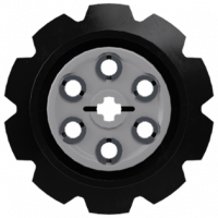
Tommy Styrvoky Posted April 13, 2018 Posted April 13, 2018 (edited) 3D printed 8 tooth sprocket by Tommy Styrvoky, on Flickr Something that I have long wanted to be a part is now a reality, as I have been doing a lot of 3D printing and modeling for my college's physics and chemistry departments. There have been so many models I have built where I had to compromise the scale due to having to size up the scale to accommodate the 10t sprocket. I have uploaded the model, for all who wish to 3D print it, the printer I used was a Lulzbot TAZ 6, as this resulted in some expansion in parts being printed in PLA, so I am unsure how well the tolerences will be if someone was to print from shapeways, as this model is intended for a cheaper FDM printer. 3D printed 8 tooth sprocket by Tommy Styrvoky, on Flickr 3D printed 8 tooth sprocket by Tommy Styrvoky, on Flickr 3D printed 8 tooth sprocket by Tommy Styrvoky, on Flickr Thingiverse link https://www.thingiverse.com/thing:2859595 I have a couple other useful ideas for parts, though I want to stay more purist with my models. Edited April 14, 2018 by Tommy Styrvoky Quote
TechnicRCRacer Posted April 13, 2018 Posted April 13, 2018 Awesome and thanks for sharing the file! I will test it on my Lulzbot Mini. Quote
Tommy Styrvoky Posted April 14, 2018 Author Posted April 14, 2018 On 4/12/2018 at 10:27 PM, TechnicRCRacer said: Awesome and thanks for sharing the file! I will test it on my Lulzbot Mini. The file is now public. Quote
MajklSpajkl Posted April 15, 2018 Posted April 15, 2018 Did you try to drive it? Even with the original it could be a bit jerky if used as a rolling wheel, I'm guessing with 8 teeth it's even worse. Then again, you probably made it to be used as driving gear :-) Quote
Tommy Styrvoky Posted April 15, 2018 Author Posted April 15, 2018 (edited) 4 hours ago, MajklSpajkl said: Did you try to drive it? Even with the original it could be a bit jerky if used as a rolling wheel, I'm guessing with 8 teeth it's even worse. Then again, you probably made it to be used as driving gear :-) Yeah my intentions are for a drive sprocket, the horrible jerky performance is true of all of the sprockets, it's just because of the the nature of the position of the track pins, they are flush with the contract surface, thus when rotating the sprocket, it causes it to be displaced vertically, Edited April 15, 2018 by Tommy Styrvoky Quote
DugaldIC Posted April 15, 2018 Posted April 15, 2018 I've just ordered a 3D printer for my own personal use so I might try making a few of these for testing. Thanks for sharing. Quote
TechnicRCRacer Posted April 16, 2018 Posted April 16, 2018 (edited) Just printed it and it works great! Thanks for sharing! @DugaldICWhat printer did you get? Edited April 16, 2018 by TechnicRCRacer Quote
DugaldIC Posted April 16, 2018 Posted April 16, 2018 22 hours ago, TechnicRCRacer said: @DugaldICWhat printer did you get? I purchased a Tevo Tornado, still waiting for it to arrive. Fingers crossed later this week. Quote
AFOLegofan66 Posted April 17, 2018 Posted April 17, 2018 Thanks very much for making this file! I will be using this for drive gears for some moc’s...let you know how it goes!! Quote
Tommy Styrvoky Posted April 17, 2018 Author Posted April 17, 2018 (edited) If anyone wants to create their own parts, these are the parts I used in Autodesk Fusion 360 to cut the holes for the axles and the pins. Fusion 360 is free for students and makers, so basically anyone who won't be using it for a large business. The basic dimensions for a technic liftarm are 7.8mm tall*7.25 wide( when looking directly at the pin holes from the side, and spacing between holes is 8mm. https://www.bricksafe.com/pages/Tommy_styrvoky/cad3d-printed-parts Edited April 17, 2018 by Tommy Styrvoky Quote
TechnicRCRacer Posted April 17, 2018 Posted April 17, 2018 35 minutes ago, Tommy Styrvoky said: If anyone wants to create their own parts, these are the parts I used in Autodesk Fusion 360 to cut the holes for the axles and the pins. Fusion 360 is free for students and makers, so basically anyone who won't be using it for a large business. The basic dimensions for a technic liftarm are 7.8mm tall*7.25 wide( when looking directly at the pin holes from the side, and spacing between holes is 8mm. https://www.bricksafe.com/pages/Tommy_styrvoky/cad3d-printed-parts Thanks soooo much for these files! I have been using Fusion 360 for a little while, and these help tremendously! @DugaldICNice! Hope it runs well! Quote
Recommended Posts
Join the conversation
You can post now and register later. If you have an account, sign in now to post with your account.