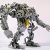
artyom_n Posted April 22, 2016 Posted April 22, 2016 (edited) Teaser: Introduction The article describes the experience of using the Lego Mindstorms EV3 set for creating a robot prototype with software and manual control via Robot Control Meta Language (RCML). Next, we will discuss the following key points: Assembly of the robot prototype from the Lego Mindstorms EV3 set. Quick RCML installation and configuration for Windows. Robot software control based on EV3 controller. Manual control of the robot peripherals using a keyboard and a gamepad. Jumping a little ahead, I will add that for implementing control over a Lego robot via a keyboard, one will have to create a program containing only 3 lines of code. More information about it is available under the cut. Step 1 First, the Lego Mindstorms EV3 set was used for creating a prototype robot to be used for programming and manual piloting. The robot's design is similar to that of a truck chassis. Two motors installed on the frame have one common rotation axis connected to the rear wheels via a gearbox. The gearbox converts the torque by increasing the angular speed of the rear axle. The steering system is assembled on the base of a bevel gear speed reducer. Step 2 The next step is RCML preparation for working with the Lego Mindstorms EV3 set. Download the archives with executable files and library files rcml_build_1.0.6.zip and rcml_modules_build_1.0.6.zip. The following describes the quick start procedure for ensuring interaction between RCML and the Lego robot controlled by an EV3 controller. Content directory after extracting the archives Next, one has to create configuration file config.ini to be placed in the same directory. To implement control over the EV3 controller via a keyboard and a gamepad, connect modules lego_ev3, keyboard and gamepad. Listing of configuration file config.ini for RCML [robot_modules] module = lego_ev3 [control_modules] module = keyboard module = gamepad Next, the EV3 controller should be paired to the adapter. The instruction for pairing an EV3 controller to a Bluetooth adapter: The reference guide contains an example of pairing a Lego Ev3 controller to a PC running under Windows 7 operating system. Next, go to the Ev3 controller settings and select menu item "Bluetooth". You should make sure that you have set the configuration settings. “Visibility” and” Bluetooth” should be ticked. Go to "Control Panel", select "Devices and Printers", and "Bluetooth Devices". Click on the "Add device" button. A window with available Bluetooth devices will open. Select "EV3" device and click "Next". Dialog box "Connect?" will be displayed on the EV3's screen. Check as appropriate and confirm by pressing the center key. Next, the "PASSKEY" dialog will be displayed, enter digits "1234", and confirm the key phrase for pairing the devices by pressing the center key at the position with the tick image. In the pairing wizard of the device, a form for devices pairing key will appear. Enter "1234" and press "Next". A window with confirmation of successful device connection will appear. Press the "Close" key. At the PC, return to "Control Panel", select "Devices and Printers", and "Bluetooth Devices". The paired device will be displayed in the list of available devices. By double clicking, go to “EV3” connection properties. Next, go to the "Hardware" tab. By double clicking, go to the connection properties of the "Standard Serial over Bluetooth link". The COM port index specified in the properties should be used in the config.ini configuration file of the lego_ev3 module. The example shows Bluetooth connection properties of a Lego EV3 controller with the use of a standard serial port COM14. Further module configuration is limited to specifying the address of the COM port used for communication with the Lego robot in the configuration file of the lego_ev3 module. Listing of configuration file config.ini for the lego_ev3 module [connections] connection = COM14 [options] dynamic_connection = 0 Now configure the keyboard module. The module is located in the control_modules directory, then keyboard. Create configuration file config.ini next to the keyboard_module.dll file. Before creating a configuration file, specify the actions to be performed by pressing keys. The keyboard module allows using keys with a certain numeric code. The table of virtual key codes is available here. As an example, I will use the following key press events: The up/down buttons are used to rotate the rear wheels motor forward/backward. The left/right arrows turn the wheels left/right The configuration file of the keyboard module describes which axes are available for the programmer to implement interaction with the robot in the manual mode. Thus, in the example we've got two control groups - these are keyboard axes. To add a new axis, stick to the following rules of axes description. Rules for describing axes for the keyboard module. 1. In case of adding a new axis, add axis name property to section [mapped_axis] and set it equal to the value of the keyboard key in HEX format; there may be several keyboard button values for one axis. In general, an entry in the [mapped_axis] section will look as follows: axis_name = keyboard_button_value_in_HEX_format 2. You should set the maximum and the minimum values that the axis may take. To do so, add to the config.ini configuration file a section named as the name of the axis, and set the upper_value and lower_value properties for passing the values of the axis' maximum and minimum. In general, the section looks as follows: [axis_name] upper_value = the_max_axis_value lower_value = the_min_axis_value 3. Next, you should determine what value the axis will have after a previously defined button on the keyboard is pressed. The values are defined by creating a section with the name consisting of the axis name and the value of keyboard button in Hex format, separated by underscores. To set the default (not pressed) and pressed state values, unpressed_value and pressed_value are used, where the values are passed. In general, the section in this case will look as follows: [axis_name_keyboard_button_value_in_HEX_format] pressed_value = axis_value_with_pressed_button unpressed_value = axis_value_with_released_button To implement the control over the robot prototype, a configuration file of the keyboard module has been created, which includes the "go" and "rotate" axes. The "go" axis is used to indicate the direction of robot movement. When the “up arrow” button is pressed, the axis is set to 100, and when the “down arrow” button is pressed, the axis is set to -50. The rotate axis is used for setting the front wheels turn angle. When the "left arrow" button is pressed, the axis is set to -5, and when the "right arrow" button is pressed, the axis is set to 5. Listing of configuration file config.ini for the keyboard module. [mapped_axis] go = 0x26 go = 0x28 rotate = 0x25 rotate = 0x27 [go] upper_value = -100 lower_value = 100 [rotate] upper_value = -100 lower_value = 100 [go_0x26] pressed_value = 100 unpressed_value = 0 [go_0x28] pressed_value = -50 unpressed_value = 0 [rotate_0x25] pressed_value = -5 unpressed_value = 0 [rotate_0x27] pressed_value = 5 unpressed_value = 0 Next, for control implementation using a gamepad, configure the gamepad. Configuring the module includes creating configuration file config.ini next to gamepad_module.dll in the control_modules directory, followed by gamepad. Listing of configuration file config.ini for the gamepad module. [axis] Exit = 9 B1 = 1 B2 = 2 B3 = 3 B4 = 4 L1 = 7 L2 = 5 R1 = 8 R2 = 6 start = 10 T1 = 11 T2 = 12 RTUD = 13 RTLR = 16 LTUD = 15 LTLR = 14 arrowsUD = 17 arrowsLR = 18 [b1] upper_value = 1 lower_value = 0 [b2] upper_value = 1 lower_value = 0 [b3] upper_value = 1 lower_value = 0 [b4] upper_value = 1 lower_value = 0 [L1] upper_value = 1 lower_value = 0 [L2] upper_value = 1 lower_value = 0 [R1] upper_value = 1 lower_value = 0 [R2] upper_value = 1 lower_value = 0 [start] upper_value = 1 lower_value = 0 [T1] upper_value = 1 lower_value = 0 [T2] upper_value = 1 lower_value = 0 [RTUD] upper_value = 0 lower_value = 65535 [RTLR] upper_value = 0 lower_value = 65535 [LTUD] upper_value = 0 lower_value = 65535 [LTLR] upper_value = 0 lower_value = 65535 [arrowsUD] upper_value = 1 lower_value = -1 [arrowsLR] upper_value = 1 lower_value = -1 Step 3 The next step is writing a program in the RCML language. At the root of the created directory, create the program file. The name and extension of the program file may be anything, however, Cyrillic characters are to be avoided. In the example, the filename is hello.rcml. For the lego_ev3 module, the robot redundancy program code looks like: @tr = robot_lego_ev3; The lego_ev3 module connection page contains description of the majority of the features supported by the controller. As a test example, a program for automatic robot drifting has been created. The algorithm of the program is as follows: function main() { @tr = robot_lego_ev3; //Reservation robot @tr->setTrackVehicle("B","C",0,0); //Installing the engine synchronization @tr->motorMoveTo("D",100,0,0); system.sleep(500); @tr->trackVehicleForward(-100); system.sleep(1000); @tr->motorMoveTo("D",50,-50,0); system.sleep(4000); @tr->motorMoveTo("D",50,50,0); system.sleep(4000); @tr->trackVehicleOff(); system.sleep(1000); } After reserving the first available robot, two motors are paired for further operation as one. After that, the robot starts drifting. Program description of robot actions makes it possible to precisely set front wheels turn angles and rear wheels rotation speed. Using this method allows achieving the results that are difficult to replicate by manual piloting from a keyboard or a gamepad. The program is compiled in the windows command line. First, navigate to the new directory with the rcml_compiler.exe and rcml_intepreter.exe executables. Then enter the following commands. The command for compiling the hello.rcml file: rcml_compiler.exe hello.rcml hello.rcml.pc The result of compilation is a new hello.rcml.pc file in the created directory. Now make sure the EV3 controller is enabled, and paired to the Bluetooth adapter. A gamepad should be connected to the PC. After that, run the program file execution command: rcml_intepreter.exe hello.rcml A video showing the robot motion program is located below this article. Step 4 The next step is controlling the robot manually, using a keyboard. The following describes the process of software pairing of robot motors to the keyboard. Keyboard can be used for controlling any motor of the robot. Within the framework of the example, control over the following mechanisms has been implemented: Front wheels turn angle, Direction of rear wheels rotation. The algorithm of the program is as follows: function main() { @tr = robot_lego_ev3; @tr->setTrackVehicle("B","C",0,0); system.hand_control(@tr,"keyboard", "straight","go", "speedMotorD","rotate"); } Then the program should be compiled and executed. The result of manual controlling a Lego robot via a keyboard is shown in the video at the bottom of the page. Step 5 In addition to the keypad module, the gamepad module is available, which makes it possible to manipulate the robot using the gamepad. For implementing control over the robot via a gamepad, one should describe at the program level what axes of the robot will be set to the values of the gamepad axes. The algorithm of the program is as follows: function main() { @tr = robot_lego_ev3; @tr->setTrackVehicle("B","C",0,0); system.hand_control(@tr,"gamepad", "straight"," RTUD", "speedMotorD"," RTLR"); } Then recompile the program and execute it. Below is the result of manual control over a Lego robot via a gamepad, and all previously connected methods: Control Lego Ev3 by using RCML The article briefly shows only certain RCML features. A more detailed description is available in the reference guide. Edited April 25, 2016 by artyom_n Quote
artyom_n Posted April 25, 2016 Author Posted April 25, 2016 UP. Load more screenshots and photos. Fixed links to video Please give me your feedback! Quote
Beard Posted April 25, 2016 Posted April 25, 2016 Thanks for taking the time to write this. If I wouldn't be so busy with work at the moment, I'd give it a try at once. Isee there's some delay with the Myo control, but that's probably because of the complex stack of control software. May I ask what kind of latency there is with the gamepad? It's a bit difficult to see in the video, but latency seems quite ok. Quote
Recommended Posts
Join the conversation
You can post now and register later. If you have an account, sign in now to post with your account.