Search the Community
Showing results for tags 'chassis'.
Found 38 results
-

WIP On-Road to Off-Road Chassis conversion
CrazyKreations posted a topic in LEGO Technic, Mindstorms, Model Team and Scale Modeling
Hey everyone, I stripped down my Dodge Demon MOC to the chassis and I want to modify it in a way that will make it look more rugged and potentially even have some RC components added! Do you all have any suggestions that you could please give to support the build?????? Here is a before and after of the chassis as of today: The Changes I have made are the following: - Improved central ground clearance - Components of the chassis have been removed to allow the fitment of bigger tyres - Larger Tires - Some reinforcement of the suspension struts and how they connect to the chassis I have a workbench post on rebrickable with a video! https://rebrickable.com/users/CrazyKreations/workbench/6109/ What should I add or change next????? -
Offroad Vehicle Design bible
Zerobricks posted a topic in LEGO Technic, Mindstorms, Model Team and Scale Modeling
I started this project because I wanted to share my experiences building various offroad models over the last decade. This topic is meant to guide the builders with comparisments, suggestion and best building practices, It is however not a place to find already finished and perfected designs - that's up to you. Various aspects of the design of the vehicles will be split into several subgroups and explained in details. 1. Number of wheels First thing we need to know is how many wheels our design will have. Most common setups are as following: 4x4 Setup Advantages: 1. The simplest and most widely setup 2. Having only 4 wheels means lower weight and higher performance 3. Higher manoeuverability 4. Simple suspension and driveline design Disadvantages: 1. With only 4 wheels the suspension has to be designed to be as flexible as possible to get the most out of the wheels 2. In a case of a mechanical failure of a single wheel, the whole model's performance is greatly affected 6x6 Setup with double rear axles Advantages: 1. Two rear axle provide more traction area, especially when going uphill 2. Usually 6x6 vehicles are longer than 4x4 and therefore less likely to tip over 3. Since the front and second axle are usually closer than in 4x4 setup, there is less ground clearance needed between them 4. Greater redundancy in a case of a mechanical failure Disadvantages: 1. Lower manoeuverability due to a longer wheelbase even with rear wheel steering 2. More complex driveline and suspension design is required 8x8 or more wheels setup Advantages: 1. Having 8 or more allows for much greater traction area 2. Ability to drive over ditches 3. Because wheels are usually much closer there is much less chances of getting stuck on top of an obstacle 4. Excellent redundancy in a case of a mechanical failure 5. Better weight distribution 6. Less suspension travel required per each wheel as with 4x4 or 6x6 and hence better stability Disadvantages: 1. Lower manoeuverability even with rear wheel steering 2. Powering 8 or more requires a very complex driveline 3. Depending on a driveline, combined torque required for powering all 8 wheels can destroy gears if a single wheel gets stuck 2. Type of wheels and tyres Now that we decided on how many wheels we want for our offroad beast, we have to look into what type of tyres and wheels we want to use. I will hereby cover only the bigger types of tyres and wheels. 1. 94.8x44R Advantages: 1. Low weight 2. Good thread design 3. Low rolling resistance Disadvantages: 1. Low traction, these tyres are prone to slip on the rim at high loads 2. Due to its rounded shape the tyres tend to slide off obstacles when crawling over them 2. 94.3x38R Advantages: 1. Low weight 2. Medium traction 3. Low rolling resistance 4. Realistic design and proportions Disadvantages: 1. Shallow thread pattern 2. These tyres are very hard and don't adjust to the terrain 3. 107x44R Advantages: 1. Low weight 2. Medium traction 3. Very deep thread 4. Currently largest tyres by diameter Disadvantages: 1. High rolling restistance and vibrations due to the thread pattern 2. These tyres are a bit hard and don't adjust to the terrain 4. Power Puller tyres Advantages: 1. High traction 2. Good thread 3. Largest Lego tyres ever produced 4. Deep wheel offset Disadvantages: 1. High weight 2. Hard to use, they require complex hub assemblies 3. Very rare and expensive 5. Outdoor challenger wheels Advantages: 1. Very high traction 2. Very good thread pattern 3. Deep wheel offset 4. Over 7 studs of space inside the wheel Disadvantages: 1. High weight 2. Hard to attach to the standard axles 3. They require a lot of torque to use them at their full potential. 6. Tumbler wheels Advantages: 1. Low weight 2. High traction 3. Very flexible Disadvantages: 1. Low thread pattern 2. Small size 3. Expensive For the 94.8x44R. 94.3x38R and 107x44R tyres we have a choice of two wheels: 1. Racing wheel large Advantages: 1. Good mounting option with axlehole and pinhole 2. Available in multiple colours 3. Cheap Disadvantages: 1. No inside wheel offset means steering pivot point can't be placed inside the wheel. 1. Futuristic wheel Advantages: 1. Deep wheel offset allows us to place steering pivot point inside or closer to the wheel than racing wheel large 2. Slightly larger wheel size stops the 94.8x44R tyre from slipping on the rim Disadvantages: 1. Limited mounting options, with only one axlehole 2. Hard to find 3. Hubs Now that we have our wheels and tyres we need a way to mount and power them. Here are the most common currently available options: 1. New standard ungeared CV hubs These hubs are usually driven by the CV joint counterpart which pops inside Advantages: 1. Low steering pivot offset - usually at the edge of the tyre: 2. Firm wheel mounting 3. Readily available, easy to use and to build on. Disadvantages: 1. Low operating angle - the CV joint can operate to a maximum of about 30 degrees, which limits steering angle. 2. Very low torque transfer - the CV joints are prone to deforming and popping out even with low torque applies to them 3. Low ground clearance 2. Old ungeared CV hubs Advantages: 1. Low steering pivot offset - usually at the edge of the tyre 2. Firm wheel mounting 3. Better ground clearance than newer hubs Disadvantages: 1. Very low operating angle - the CV joint can operate to a maximum of about 25 degrees, which limits steering angle. 2. Very low torque transfer - the CV joints are prone to deforming and popping out even with low torque applies to them 3. Hard to find and expensive 4. No other mounting points than 4 ball joints 3. Built cardan ungeared hubs Example of a hub using a cardan joint to directly transfer the power to the wheel Advantages: 1. Low steering pivot offset - usually at the edge of the tyre 2. Easy to build 3. Can transfer higher torque than a CV joint 4. Higher steering angle Disadvantages: 1. Mounting relies only on the axle and is not as firm as standard hubs 2. Not capable of transferring high torque to the wheels 3. Low ground clearance 4. Standard portal hubs Advantages: 1. Easy to use and to build on. 2. Can transfer very high torque to the wheels when using 8z and 24Z gear combination 3. High steering angle 4. High ground clearance 5. Firm wheel mounting Disadvantages: 1. Very high steering pivot offset - requires stronger steering mechanisms and more fender space for wheel to swing 5. Built portal hubs Advantages: 1. Easy to build. 2. Can transfer very high torque to the wheels when using 8z and 24Z gear combination 3. High steering angle 4. Higher ground clearance than standard portal hubs 5. Low steering pivot offset when using futuristic wheels Disadvantages: 1. Wheels are mounted and held only by one axle, not as firm as standard hubs 2. Hub relies on friction of the components to keep it together, which can slide apart after prolonged use 6. Built planetary hub Advantages: 1. Highest gear ratio of all other hubs, 1:4 2. Firm wheel mounting when using futuristic of power puller wheels 3. High steering angle 4. Lower steering offset than standard portal hubs Disadvantages: 1. Requires old turntable, futuristic or power puller wheels for best results - all are hard to find 2. High number of moving gears 3. Least efficient due to the high friction caused by the large surface contact area and number of moving gears 4. Suspension Suspension is the mechanism that will keep our model's wheels in contact to the ground and will be supporting most of its weight. Most of the designs cover 4x4's Following factors determine the type of suspension system we will use: 1. Weight of the model - The heavier the model, the stronger the suspension components have to be 2. Speed - Faster models require more responsive suspension systems with low unsprung weight 3. Flexibility - The higher the obstacles you want to climb over the more flex and/or wheel travel suspension has to provide 1. No suspension I have yet to see and offroad vehicle without any type of suspension (except for maybe 42070, 42081 and 42082), but I will list my opinion regardless: Advantages: 1. Simple design - having no suspension simplifies our design...and that's about it Disadvantages: 1. No flex over terrain means, there are only 3 wheels at once touching the ground 2. Low stability 3. Poor weight distribution 4. No shock absorption at high speeds 2. Pendular suspension This is the simplest suspension you can put on your vehicle. It basically means one or more of your axles are free to swing about. When using this suspension I suggest using the small turntable where drive axle enters the axle. This will keep the drive axle from carrying the weight of the model, which causes unnecessary friction. 42030 is a typical example of this suspension system. Advantages: 1. Simple, robust design 2. Using this suspension on both axles can give the model very high flexibility 3. If there are no springs used, the model can have perfect weight distribution on left and right wheel Disadvantages: 1. Large unsprung weight, poor responsivness at high speeds 2. No shock absorption means this suspension is not suitable for high speeds 2. When using on one axle, the stability of the whole model relies on the unsuspended axle. 3. When using pendular suspension on both axles springs or a transfer mechanism are required to keep the model upright 3. Single torque tube suspension This suspension became available with the release of the 8110 Unimog. Best examples of this suspension are 8110, 9398 and 41999. It is the simplest suspension which also allows for vertical suspension movement. Advantages: 1. Simple, robust design 2. Universal joints can be placed inside the ball joint, allowing power to be transferred to the axle 3. Easy to implement Disadvantages: 1. Large unsprung weight, poor responsivness at high speeds 2. Axle requires a some kind of a linkage system to keep it cenetred (panhard or parallel links as seen above). 3. Using this suspension on the front axle usually results in negative caster angle which causes higher rolling resistance 4. When used on rear drive axle, the suspension has the tendency to cause oscillate, especially with soft suspension and high power 4. Hard to connect springs to the chassis 4. Double torque tube suspension This is an evolution of the single torque tube suspension, which uses two ball joints to drive each wheel side respectively. It is my own original idea. Advantages: 1. Simple, robust design 2. Universal joints can be placed inside the ball joint, allowing power to be transferred to the axle 3. Easy to implement 4. Self-cenetring, since axles are connected in the center there is no need for linkages to center it 5. Can carry power to each wheel side independently 6. Drive torque compensation Disadvantages: 1. Large unsprung weight, poor responsivness at high speeds 2. Using this suspension on the front axle usually results in negative caster angle which causes higher rolling resistance 3. When used on rear drive axle, the suspension has the tendency to cause oscillate, especially with soft suspension and high power 4. Hard to connect springs to the chassis 5. Parallel floating axle This suspension uses linkages which keep the axle parallel to the chassis of the model. For best functionality and reliability the lengths of all links and that of the double cardan joint should be equal. Also all the linkages and drive axles should be parallel. Advantages: 1. Keeping the axle parallel to the chassis reduces the oscillations effect 2. Better responsivness compared to the torque tubes 3. Neutral caster angle when used on front axles. 4. Self cenetring when using A arm as upper link or 4 link setup 5. Can be configured to carry power to each wheel side independently 6. If configured to carry power to each wheel side independently the drive torque can be compensated. 7. Easy to connect spring to the chassis Disadvantages: 1. High unsprung weight, less responsive at high speeds 2. Increased mechanical complexity, double cardan joints required to carry the power to the axle 6. Half axle independent suspension This is the simplest independent suspension you can build. Best example of such suspension are Tatra and Pinzgauer trucks. Advantages: 1. Independent suspension with low unspring weight, suitable for high speed 2. Robust design with low number of moving parts 3. Easy to connect spring to the chassis Disadvantages: 1. Changes of the caster angle as the wheels travel up and down 2. Hard to implement a drive system that does not carry the weight of the vehicle 3. Hard to implement steering system 4. Wheels tend to drag sideways on the ground when suspension travels up and down, reducing efficiency 7. Trailing arm parallel independent suspension Personally I have not used this suspension yet, but I did use a normal trailing arm suspension which does not keep the hubs parallel. Normal trailing arm suspension which does not keep the hubs parallel acts similarly to torque tube suspension. For the prallel version of the trailing suspension I imagine the following: Advantages: 1. Independent suspension with low unspring weight, suitable for high speed 2. Robust design with low number of moving parts 3. Long links allow for high suspension travel 4. Very easy to connect spring to the chassis 5. Can be configured to carry power to each wheel side independently Disadvantages: 1. Hard to keep the wheels from sagging under the weight of the model. 2. Difficult to transfer power to the wheels 8. Double wishbone suspension This suspension uses two A-shaped arms to keep the wheel hubs in place. As of late it's my favourite suspension system due to: Advantages: 1. Independent suspension with low unspring weight, suitable for high speed 2. Very customizable design with lots of adjustable characteristics (suspension arm lengths, caster angle, camber angle, steering geometries) 3. When build correctly it is far more robust than live axle suspension 4. Increased ground clearance compared to live axle suspension, especially when used with portal hubs 5. Can be configured to carry power to each wheel side independently 6. Extremely easy mounting of springs 7. Very stable compared to live axles 8. Frame holding the suspension can be part of the chassis, therebye lowering the center of gravity Disadvantages: 1. More moving parts as live axle suspension, increased mechanical complexity 2. Limited wheel travel - Lego wishbones allow a max. of around 25 degrees of suspension angle 9. Multi-link suspension To be updated when I build my first multi-link offroad suspension. I can assume the following characteristics: 1. Independent suspension with low unspuing weight, suitable for high speed 2. Extremely customizable design with lots of adjustable charactersitics (suspension arm lengths, caster angle, camber angle, steering geometries, virtual pivot point) 3. Large steering pivot point compensation 4. Increased ground clearance compared to live axle suspension, especially when used with portal hubs 5. Can be configured to carry power to each wheel side independently 6. Very stable compared to live axles 7. Frame holding the suspension can be part of the chassis, thereby lowering the center of gravity Disadvantages: 1. Very high amount of moving parts, increased mechanical complexity 2. Limited wheel travel - Lego wishbones allow a max. of around 25 degrees of suspension angle 3. Hard to connect springs to the chassis 10. Spring types Listed below are the most common types of springs available: 6.5L Soft shock absorber Advantages: 1. Small, easy to implement Disadvantages: 1. One stud of suspension travel 2. Low spring rate, can't support heavy models 6.5L Hard shock absorber 1. Small, easy to implement 2. High spring rate, can support heavy models Disadvantages: 1. One stud of suspension travel 9L soft shock absorber When using 9L shock absorbers I suggest you do not use the default offset upper attachment point, but use an in-line attachment point instead. This will reduce the friction and allow for better high speed performance Example: Advantages: 1. Two studs of suspension travel 2. More attachment possibilities than 6.5 L shock absorber Disadvantages: 1. Default attachment points create friction 2. Low spring rate, can't support heavy models 9L hard shock absorber Advantages: 1. Two studs of suspension travel 2. More attachment possibilities than 6.5 L shock absorber 3. High spring rate, can support heavy models Disadvantages: 1. Default attachment points create friction 2. Rare and expensive 11. Attaching springs to live axles If we start with basics, the first things we have to check is how position of springs affects suspension of live axles. The closer you place the springs together, the more flex the suspension will have, but it will also be less stable: I suggest you to keep springs at a distance of around 1/2 of the total model width. When placing springs you should keep them in-line with the wheel bearing in order to reduce friction. First example of bad spring placements: And example of good spring placement: When using multiple springs make sure to place them symmetrically centrred to the wheel hub: When attaching springs to torque tube suspension, you have to allow springs to tilt in two planes: You can also attach the springs to the suspension links to increase suspension travel. This technique is especially common on Trophy Trucks: 12. Attaching springs to independent suspension Independent suspension allows for much more flexible spring placement. Generally the closer you attach the spring to the main suspension arm pivot, the higher spring travel you get, but lower suspension force. Examples going from the hardest suspension with low travel to the softest with high travel: You can also attach springs inside the suspension arms: Or horizontally: As with the live axles make sure springs are in the center of the wishbones. Example of good placements: And an example of bad spring placement, which causes excessive friction and suspension binding: 5. Steering Steering is the system which allows our model to change direction. Generally there are two types of steering system used: 1. Skid steering Advantages: 1. Very simple to implement and control with two separate motors for left and right sided wheels. 2. Does not require a dedicated steering motor Disadvantages: 1. Not efficient, since wheels have to skid to steer 2. Power had to be reduced or even reversed in order to steer. 3. Not very accurate 4. Not very effective offroad 2. Classical steering with steerable wheels Advantages: 1. Efficient, with minimum loss of speed 2. Accurate 3. Does not reduce the power of the drive motors 4. Can be used in front, rear or all axles for tight steering radius or crab steering 5. Effective offroad Disadvantages: 1. Requires more complex hub assemblies 2. For best steering accuracy you need a dedicated servo motor. Examples of a simple classical steering system for live axles 1. Parallel steering system for live axles Here both hubs are always parallel. Position of the steering in the front or rear rack has no affect on the steering. Advantages: 1. Very simple and robust 2. Easy to build Disadvantages: 1. No Ackermann steering geometry 2. Steering rack moves inwards as it steers, requiring more space. 2. Ackermann steering system for live axles This system allows the hubs to steer at different rates. The steering arms are offset inside so they form a virtual steering point where at the point where lines meet. Advantages: 1. Better steering performance Disadvantages: 1. More complex assembly 2. Steering rack moves inwards as it steers, requiring more space. 3. Steering system with diagonal linkages This system acts similar as Ackermann steering system by using diagonal steering links. Advantages: 1. Better steering performance 2. Steering rack only has to move in one direction without sideways movements 3. Can be configured to be used in front or the rear of the axle. Disadvantages: 1. More complex assembly 4. Simple steering system for independent suspension 1. Very simple and robust 2. Easy to build 3. Can be even more robust when using double steering racks and links 4. Steering rack only has to move in one direction without sideways movements Disadvantages: 1. No Ackermann steering geometry 5. Ackermann steering system for independent suspension Advantages: 1. Better steering performance 2. Steering rack only has to move in one direction without sideways movements Disadvantages: 1. More complex assembly, less robust. 3. General steering tips 1. When using independent suspension always make sure your links are paralel to the suspension arms, otherwise you may end up with wheels which are not parallel and are causing excessive friction: 2. When using standard portal hubs make sure your steering system is robust enough to deal with the forces generated by wheel driving into obstacles. 3. If possible use servo motors which allow for high steering precision and return to center. They are especially useful at high speed models. 4. Most efficient way to steer the wheels is using the steering racks. 5. Build axles in such way they have positive caster angle, example for direction of travel from right to left. This will self-center your wheels and reduce rolling resistance. 6. Drivelines Drivelines are the responsible for transferring the power from the motors to the wheels. There are various drivelines you can build, here I listed few with their characteristics: Driveline types 1. Permanent 4x4 Advantages: 1. Simple, centralized, low mechanical complexity 2. Wheels are always powered, great offroad performance 3. Light weight Disadvantages: 1. Poor steering radius 2. Tyres have to skid when steering, lowering efficiency of the model 2. 4x4 with open differentials Typical example of this driveline is 42070 Advantages: 1. Differentials allow the wheels to so spin at different rates when steering 2. Very efficient since wheels don't have to skid when steering Disadvantages: 1. If one wheel loses traction, all the power is transfereed to it, poor offroad performance 3. 4x4 with lockable differentials Advantages: 1. Differentials allow the wheels to so spin at different rates when steering 2. Very efficient since wheels don't have to skid when steering 3. All differentials can be locked, so wheels are powered for great offroad performance Disadvantages: 1. Higher mechanical complexity 2. Dedicated motor is required to actuate differential locks, higher weight 4. Axle mounted motors Typical example of this driveline are 9398 and 41999. Advantages: 1. Differentials allow the wheels to so spin at different rates when steering 2. Very efficient since wheels don't have to skid when steering 3. If one wheel gets off the ground the second axle can still pull/push the model. Disadvantages: 1. Higher mechanical complexity 2. Usually the rear axle motor is more loaded than the front, especially when climbing uphill, the motors can't "help" each other. 3. Worse offroad performance than permanent 4x4 5. H drive: This is my favourite driveline due to the following reasons: Advantages: 1. Motors allow the wheels to so spin at different rates when steering 2. Model can skid steer 3. Very efficient since wheels don't have to skid when steering normally 4. Having 2 drivelines allows you to carry more torque to the wheels 5. Redundancy, even if one drive fails the model can still move 6. Wheels are always powered, great offroad performance Disadvantages: 1. Higher mechanical complexity 2. Slightly higher weight 6. Wheel motor drive Each motor powers a wheel independently. Advantages: 1. Motors allow the wheels to so spin at different rates when steering 2. Model can skid steer 3. Very efficient since wheels don't have to skid when steering normally 4. Redundancy, even if one or more motors fails the model can still move 6. Lower mechanical complexity Disadvantages: 1. Motors can't "help" each other 2. Higher weight due to a higher motor count Transferring power axially When transferring power via axles, you can reduce the flex by using connectors instead of simple "bare" axle: Use axles with stops to prevent them from sliding out of gears: Where possible always brace tooth gears from both sides: Transferring power at an angle Where pairs of U joints are used, make sure to align them to eliminate vibrations: Brick built CV joint which can transfer high torque at over 30 degrees angle Brick built cardan joint which can transfer extremely high torque up to 15 degrees angle Brick built flexible drive which can transfer medium high torque, extract and retract, suitable for low angles Transferring power perpendicularly The following perpendicular gearboxes are the best suitable for transferring high torque Avoid knob and worm gears, because they waste energy Gearboxes In my models I generally use the following gearboxes: 1:3 differential gearbox Advantages: 1. Very high gear ratio between low and high gear, 1:3 2. Capable of transferring high torque 3. Very efficient since only 2 gears are used at any time Disadvantages: 1. Takes a lot of space 2. This gearbox requires a good housing to brace the gears properly Compact two speed gearbox Advantages: 1. High gear ratio between low and high gear, 1:2,77 2. Capable of transferring high torque 3. Very efficient since only 2 gears are used at any time 4. Very compact design Disadvantages: 1. Requires two of the rare 20 tooth clutch gears 2. More complex shifter assembly. Diagonal gearbox Advantages: 1. High number of gears 2. High gear ratio possible, over 4:1 2. Capable of transferring high torque 3. Very efficient since only 2 gears are used at any time Disadvantages: 1. Takes a lot of space 2. Input and output axles are not parallel. 3. A complex shifting assembly is required for sequential operation. Driveline effect on suspension Transferring torque on the wheels can affect the suspension, especially when live axles are used. The following photo shows how the torque causes one side of the axle to push down and the other to lift up: In order to minimize this effect I suggest the following: 1. Make sure to have most if not all the downgearing inside the axles, so you do not need high torque going to the axles. 2. Make sure your models have a low center of gravity 3. You can eliminate this effect by using two counte rotating axles which cancel each other's torque, example below: 7. Motors and control Following are the most common types of motors used for Lego models. You can find more info here: http://www.philohome.com/motors/motorcomp.htm My personal favourites are L and RC motors due to the balanced output speed to torque ration and great mounting options. 1. PF-M Advantages: 1. High speed output 2. Smallest available motor 3. Cheap and available Disadvantages: 1. Low torque 2. Poor mounting options 2. PF-L Advantages: 1. High speed output 2. High torque 3. Cheap and available 4. Great mounting options Disadvantages: 1. Odd shape 3. PF-XL Advantages: 1. Very high torque 3. Cheap and available 4. Good mounting options Disadvantages: 1. Slow speed output 2. Large form factor 4. PF-Servo Advantages: 1. Very high torque 2. Very precise output with 15 positions 3. Good mounting options Disadvantages: 1. Slow speed output 2. Output axle can move a max of 180 degrees 3. Large form factor 4. Hard to find 5. 9V-RC motor Advantages: 1. Most oowerful Lego motor 2. Very high speed output 3. Good mounting options 4. Two output axles with different gearing ratios 5. Drive axles can pass through the motor Disadvantages: 1. Low output torque 2. Low efficiency 3. Power hungry 4. Odd form factor 5. Hard to find and expensive Power options 1. PF - AA battery box Advantages: 1. High capacity 2. Good mounting options 3. Works with rechargeable batteries, but with lower performance 4. Cheap and easy to find Disadvantages: 1. 750mA current limit - not enough to fully power RC motor 2. Heavy 3. Has to be removed and opened to replace batteries 4. Wasteful 5. Odd form factor 2. PF - LiPo battery box Advantages: 1. Small form factor 2. Light weight 3. Easy to recharge Disadvantages: 1. 750mA current limit - not enough to fully power RC motor 2. Low capacity 3. Studded design 4. Expensive and hard to find 3. RC control unit Advantages: 1. No current limit - can power 2RC motors at once 2. 3 Power levels 3. Has integrated steering output with 7 positions 4. Good mounting options 5. Easy battery replacement 6. Radio based control Disadvantages: 1. Poor quality, prone to breaking 2. Limited angle (45 degrees) and torque from the steering output 3. Has to be removed and opened to replace batteries 4. Very large form factor 5. Expensive and hard to find 6. Heavy 7. Required dedicated antennas and remote Control options 1. PF receiver and controller Advantages: 1. Receiver is easy to integrate into the model 2. Controllers have physical feedback 3. Cheap and easy to find Disadvantages: 1. IR based, low range, useless outside 2. Lack of PWM motor control, unless using train controller which is awkward to use 3. Odd form factor for use with steering 2. RC control unit See above 3. Third party options such as BuWizz and Sbrick Advantages: 1. Smaller form factors, easy to integrate into model 2. More outputs than PF system 3. Smooth control of motors 4. High range thanks to Bluetooth control 5. Higher power available with BuWizz 6. Customizable profiles Disadvantages: 1. Smart device is required 2. No physical feedback 3. Sbrick is limited by PF battery box 4. Price 8. Chassis Chasis is the backbone of your model which olds everything together. For chassis I suggest you to use the following components in order to make it strong and robust enough to deal with the stresses involved when crawling or driving at high speed: Some flex in the chassis might be a good thing to improve offroad capability, but only if id does not affect the driveline and cause friction on the drive axles. Remeember to use diagonal support, since triangles are the strongest shapes. You can also use panels and motors as structural support. Interlocking your chassis will keep it from slipping apart. For good examples of chassis designs I suggest you check the instructions for 9398 and 42083. -
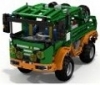
Eurobricker's share your trucks!!!!
CrazyKreations posted a topic in LEGO Technic, Mindstorms, Model Team and Scale Modeling
Hello everyone, I have been in contact with a few fellow eurobrickers and some of them have wanted a truck topic where we can all share different designs for our trucks and trailers. These designs could also include maybe some clever and effecient suggestions to show others how you made your amazing MOC! All forms of trucks are accepted tow trucks to mighty expedition trucks! Post your truck, or gain inspiration from others! For starters I will share mine: A sporty flatbed truck! -

[MOC] A 'Clean' Off Road Car Chassis
zumaidi posted a topic in LEGO Technic, Mindstorms, Model Team and Scale Modeling
A clean car chassis with remote and suspension. https://rebrickable.com/mocs/MOC-76908/zumaidi/clean-chassis/#details Car Chassis -

[MOC] Lego Technic Chilli Crawler
PunkTacoNYC posted a topic in LEGO Technic, Mindstorms, Model Team and Scale Modeling
I present to you my Lego Technic Chilli Crawler! This is a complete makeover and overall improvement from my previous Carrot Crawler: http://www.eurobrick...howtopic=112037 Yes, I know. This is the second crawler that I named after a vegetable; expect more! Features: - Triangulated 4-link live axle suspension using 4 soft, black shocks. - 4x4 with one PF XL motor mounted parallel* to each of the two axles. A final gear ratio of 1:5.001, yes this may seem slow, but the enormous Super Swamper tires make up for it. - Speaking of that, 4 RC4WD Super Swamper tires. No, they are not Lego, I got them from a nearby hobby shop. - One L-motor for steering in the front axle, geared down via worm gear to 8 tooth gear, then a 12 tooth gear to a 40 tooth gear. The 40 tooth gear drives another 12 tooth gear that moves a 13L gear rack. - Portal hubs for all four wheels. Standard Lego Unimog for the rear axle for rigidity; custom triangular plate portal hubs on front axle for a steering pivot point closer to the center of the tire. - Good articulation, about ~55-60 degrees. - Controlled with an SBrick. - Powered by a Lego rechargeable LiPo battery. - Green Chilli Stem** * The mounting of the drive motors parallel to the axles was a must for this crawler. By doing so, I have not only eliminated gear slippage as there are no perpendicular gears, but there is also a ton more ground clearance in both the front and rear axle. The rear axle especially as the motor is actually on TOP of the axle. Crazy, huh? ** Makes the crawler look so much cooler. Challenges: - As with all 4-link suspension setups, the mounting and placement of both the links and the shock absorbers proved to be a rather annoying, tedious part of the process. I have, however, managed to make a VERY rigid triangulated setup where the shocks are not bent or warped in any way. - The mounting of the two lower links on the front axle was also difficult as there was virtually nowhere I could mount these links onto. I was able to (somehow) securely mount both the lower links and the shocks of the front axle onto 7L and 9L beams on either side of the motor. - Mounting the motors parallel to the axles proved to be hard, but actually somewhat straightforward when it came to the rear axle. I had been so used to having drive axles perpendicular to the axle like on my previous crawler. The mounting of the front drive motor was difficult in the fact that its power is transmitted through various gears and the motor itself is connected to the axle by two plate beams and a pin or two. Although the front drive motor is still not completely rigid, I have had no problems with gear slippage whatsoever in either axle. Some pictures: And finally, here is the youtube video: I welcome any suggestions or comments you may have. I will, however, say in advance that I DO NOT plan on making a body for this crawler as I designed it for performance purposes mostly, a Lego "comp-crawler" as you may call it. Thanks, pt -
.thumb.png.116032e930e483fb4ebbfdc62183bd34.png)
[MOC] Rugged supercar - Hammerhead (1:9 scale) - Revisiting
Didumos69 posted a topic in LEGO Technic, Mindstorms, Model Team and Scale Modeling
Rugged supercar - Hammerhead (1:9 scale) This project was not something I started very consciously. Also for me it evolved into something special. I was especially happy with the interference (in a positive way) of other builders. A big thank you to this community, for pushing me in the right direction on several occasions! The most special part - to me - of this build, is the chassis. It combines a simple 4-speed AWD transmission, a flawless sequential shifting mechanism and advanced suspension setups with Ackermann steering, anti-roll bars, torsion bars, 2 studs ground clearance and 2 studs suspension travel. All wrapped together in a very flat yet rigid and coherent structure with a mid-console width of only 5 studs. I did not want the bodywork to make any compromises to these features. I wanted the body to continue the line of durability set in by the chassis. Flex-axles do not fit that image, hence no wheel arcs. They would also sit 2 studs above the hood - not very elegant. The result is a car that does not only look fool-proof; it is fool-proof. After a rough treatment, you don't need to tighten connections or fine-tune gears to avoid friction. You can carry the car by the sides, by the trunk door (rear wing), by the nose and by the bumpers without displacing any parts. You can even grab the 2Kg build by the roof and turn it upside down to see the bottom side without a problem. So I did not intend to level with great bodywork builders. To me the biggest compliment is that some have referred to this model as the successor of 8865 and 8880. Drive train AWD with 3 differentials Sequential 4-speed gearbox One-finger shifter V8 fake engine Suspension Double wishbone suspension Anti-roll bars (front & rear) 2 studs suspension travel 2 studs ground clearance Steering Ackermann steering Gear-rack sliders Working steering wheel HoG steering Chassis Sturdy and durable Integrated bumpers Adjustable seats Narrow mid-console (5L) Bodywork Sturdy and durable Integrated roll-cage Lockable doors Openable trunk Liftable By the roof By the sides By the nose By the trunk door Instructions are available on Rebrickable. There is a full-featured version called 'Rugged supercar' and a chassis-only version called 'Flat AWD chassis'. The chassis-only version confines itself to part 1 of the instructions of the full-featured version. Special thanks to @Blakbird and @BusterHaus - with Blakbird being the driving force - for taking on the task of making these beautiful instructions! Making instructions for a build like this is a tremendous amount of work. Even more so, given the fact that I have been very demanding in sticking to my original design. - 32005a (Link 1 x 6 without Stoppers) - used for the anti-roll bars and steering tie rods - is preferred over 32005b (Link 1 x 6 with Stoppers), because each link has tow-balls inserted from both sides. 32005b can be used too, but in that case each link will have one tow-ball that needs quite some force to insert. - 32056 (Liftarm 3 x 3 L-Shape Thin) - used for the door locks - is preferred over 32249 (Liftarm 3 x 3 L-Shape with Quarter Ellipse Thin). 32249 can be used too, but makes it more likely to accidentally lock the door while it's open, which is not a big deal of course. - 76138 (Shock Absorber 6.5L with Soft Spring) - used for the door locks - should be soft springs. They are quite rare in red, but you could also use two LBG soft springs. - 85543 (Rubber Belt Small (Round Cross Section) - used for the 90 degree limiter and the return-to-center of the gear shifter - should be relatively new, say max 2 years. Not that they wear out quickly, but the older ones are slightly less tight. Images of the full-featured version can be found here. Images of the chassis-only version can be found here. See the entry on The LEGO Car Blog! P.S. Where real cars start with a sketch, evolve into a professional design and finally have their technical details filled-in, this project started with some technical details, evolved into a complete design and ended up in a sketch ;-). By @HorcikDesigns (http://horcikdesigns.deviantart.com/gallery/). -
BuWizz Small car competition
Zerobricks posted a topic in LEGO Technic, Mindstorms, Model Team and Scale Modeling
RULES Build a body on the top of the predefined chassis. Instructions can be found here: http://bit.ly/Competition_instuctions You may extend or retract the cassis by 2 studs and change the type of wheels. Any other changes to the chassis are not allowed. You are only allowed to use unmodified Lego bricks and a BuWizz, no gluing or such allowed. You may use third party rubber bands or strings. Each participant is judged in for the following: 1. Aesthetics – the model with the best-looking body 2. Most epic stunts performed – a jump, drift, crash, chase, etc… Try your best to set up and record the most epic video of your creation. Contest voting will be held at here Eurobricks forums, each user can assign points to 6 competitors using the following formula: Contestant 1 : 10 points Contestant 2 : 6 points Contestant 3 : 4 points Contestant 4 : 3 points Contestant 5 : 2 points Contestant 6 : 1 points Competition start: 10.09.2018 Competition END: 20.10.2018 31.10.2018, 23:59 CET PRIZES: 1 st prize: 3 x BuWiz 2 nd prize: 2 x BuWiz 3 rd prize: 1 x BuWiz -
.thumb.gif.ad7c8d88b264ee812194946c07404504.gif)
[MOC] 2WD Drift Racer Chassis
mocbuild101 posted a topic in LEGO Technic, Mindstorms, Model Team and Scale Modeling
This was originally designed to be the smallest RC car to use a buggy motor, but it soon became an extremely powerful car capable of drifting. I refined the chassis design over 2 prototypes, and then tried multiple combinations of gear ratios and different sizes of wheels to achieve the best speed. The result: this MOC you are looking at right now! Driven by buggy motor, geared 1:1.25 Steered by PF servo Hidden power switch on underside LDcad/POV-Ray animation Video: http://bricksafe.com/files/mocbuild101/drift-racer-chassis/video.mpg Instructions: http://www.rebrickable.com/mocs/MOC-8835/mocbuild101/2wd-drift-racer-chassis 3D File http://www.bricksafe.com/files/mocbuild101/drift-racer-chassis/2WD Drift Racer 3D file.mpd -
1023 Speed Car MOC. A 1023 speed gearbox has been built into a remote controlled car chassis.
TechnicBrickPower posted a topic in LEGO Technic, Mindstorms, Model Team and Scale Modeling
A 1023 speed gearbox has been built into a large remote controlled car chassis. The car can be steered and driven via remote control using two channels. The gears can be manually changed using ten selectors that drive ten differentials. This allows for one of 1023 different speeds to be selected to set the car's forward and reverse speeds. The car drives well on carpet as well as a smooth surface. It uses 4 large 10cm diameter wheels and a medium sized motor for the steering mechanism. The main drive is from a large power functions motor. The gearbox functions are explained in detail. -
[MOC] RC Car Chassis - normal foward, 1/5 speed reverse
TechnicBrickPower posted a topic in LEGO Technic, Mindstorms, Model Team and Scale Modeling
Hi All, This is my first attempt at a car chassis. It is remote controlled with forward and reverse and remote controlled steering. What is different about this design is that it implements a special gearing mechanism that allows the car to drive forward at a normal speed, and 1/5 the speed in reverse. It uses a special configuration of differentials and a pair of ratchet gears to achieve this - however I did discover a flaw in the design after I built it. -

Chassis for excavators
qwest70 posted a topic in LEGO Technic, Mindstorms, Model Team and Scale Modeling
Hello! Not so long ago, I became interested Lego technic and decided to assemble my own excavator based on 8043. I began to design a chassis on Lego Disigner. And now I present to your attention a new chassis. I made it completely independent on radio control with two M motors that can be changed to L motors, and a two-speed transmission, for better cross-country ability, which is switched manually. The gear ratio is 1 : 1 and 1.5 : 1. The chassis has become 3 cm longer - it is 20 studs and 20 cm, faster and more passable than 8043. I want to know your opinions, ideas and suggestions for improvement. https://photos.app.goo.gl/pLWJAhrkLgbQsicx9 https://photos.app.goo.gl/u9BBHzmuTSy9ownA7 https://photos.app.goo.gl/UtGjoYUEW6Aj4gzc6 https://photos.app.goo.gl/pD2fxTxMAZBFhk9b6 https://photos.app.goo.gl/vCrHdsWXX5dWx3pQ8 https://photos.app.goo.gl/xFhtM5JCXkzqVDfw7 https://photos.app.goo.gl/ViqR7qVG8FfWWggM6 https://photos.app.goo.gl/TVUwKgE8TWrpRN2R8 https://photos.app.goo.gl/JFmRJjed1vA3BnP4A https://photos.app.goo.gl/AXv7u1MQ4RnDmCDV9 https://photos.app.goo.gl/HVCucWCKUY3Gae8U8 -

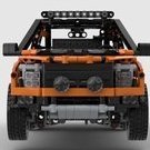
Lego Technic Toyota Land Cruiser FJ70
maciej posted a topic in LEGO Technic, Mindstorms, Model Team and Scale Modeling
Hello to all, I am new here and wanted to share my very first creation with you. This is Toyota Land Cruiser FJ70 pick-up. I build it by using bricks from following sets 42000,42030,42042,42043. I took inspiration from RM8 creations but also in the past I was driving this car quite a lot in raw conditions and I have big sentiment related with this Toyota model. Pix and Video are not pro quality as this is my very first approach to build and share LEGO creation so please don't judge me too harshly form this point of view. I hope you will enjoy looking at this model. In the near future I have plan to make simple video how to build it. Under the below links you will find pix and video. https://www.flickr.com/gp/156725712@N06/bP6n4Q Below is video instruction for Lego Technic Toyota Land Cruiser FJ70 - body (part 2). Unfortunately due to file size restriction in my camera, there is missing small part of the video where is shown how to build roof and back side of the body. However this two missing bits are easy to reproduce based on the pix. For those who would like to built this body it can be also good opportunity to put a bit of own invention. -
A smaller, studless version of the classic 853, keeping all that set's best features and losing the flaws. The idea here is to create a smaller, cheaper set so it uses around 500 pieces. 42853 by Nick Barrett, on Flickr 42853 by Nick Barrett, on Flickr The engine / transmission unit is easily removable, it runs fairly fast in forward, faster still in reverse just like the old one. Seats adjust and there's that all important rear armrest! 42853 by Nick Barrett, on Flickr 42853 by Nick Barrett, on Flickr
-

Bentley 4.5l ‘Blower’ model
BC Lego posted a topic in LEGO Technic, Mindstorms, Model Team and Scale Modeling
Hello everyone, I have built a model of one of Britains classic race cars, the Bentley 4.5l ‘Blower’, a project that was never actually approved by W.O Bentley (company founder) but nonetheless took part in the 1930 Le Mans 24hr race and French Grand Prix where it finished second behind a much more agile Bugatti type 35. Its claim to fame was not through racing victory but through its racing stories. The model has working ‘worm and wheel’ steering and a removable bonnet to expose the 4.5 litre, 4-cylinder supercharged engine. Accuracy and realism was key right from the chassis frame and the parts were spray painted to give two new green colours. For more info and images please Click here to take a look at the project on Lego Ideas. Many thanks... -

[Stud.io MOC] Trailer Chassis with Independent Suspension
BrickWild posted a topic in LEGO Technic, Mindstorms, Model Team and Scale Modeling
I'm planning on building a cargo trailer for the upcoming Land Rover Defender! Next, I might plan on building the drawbar. -
Beginner Car Chassis - Lego Mindstorms EV3
StudRobotics posted a topic in LEGO Technic, Mindstorms, Model Team and Scale Modeling
This is my simple Lego car chassis for Mindstorms and Technic beginners. Features Rack-and-pinion steering Full independent suspension 1:3 gear ratio driven to rear differential I built this chassis as both an experimental project but also an educational one to not just me but people starting to make their own cars with Mindstorms and Technic. If you're looking for a chassis design that may work for the build you're creating (a sports car, sedan, or small truck) then I hope this helps you and I would look forward to seeing the finished result. -
[MOC][WIP] Steppenwolf
Didumos69 posted a topic in LEGO Technic, Mindstorms, Model Team and Scale Modeling
UPDATE: Thanks to an amazing effort by Thorsten Spelz full-blown building instructions are now available on Rebrickable! UPDATE: I updated building directions to reflect some improvements to the front suspension. See entry #30 of this topic. Hello, I started a topic on my 'Steppenwolf'-project before, but that post feels a little bit like a false start by now. At that stage I only had digital ideas and there where some correct critiques about the designs I showed, especially about the custom wheel hubs. Since than I thoroughly redesigned the front and rear suspension and about a month ago I started building my 'Steppenwolf'-chassis. Now I have come to a point to show the first 'real life' results and I would like to use this topic to show progress and to elaborate further on specific parts of the concept. First of all it was a real sensation to start building with real bricks after 25 years of not 'playing' with lego. To show a little bit of where I come from when it comes to Lego Technic: this is my last build from about 25 years ago: https://bricksafe.co...jpg/800x600.jpg https://bricksafe.co...jpg/800x600.jpg With the 'Steppenwolf'-project I aim for an AWD platform that can serve as the base of a push-along car. It is meant to fit 'ordinary' AWD cars rather than Baya truck-like vehicles. The platform combines all-wheel-drive with Ackermann steering, progressive camber angle, caster angle, kingpin inclination, 4 stud suspension travel and 5 stud clearance (with 94.8 x 44 R balloon tire). As suspension and drive characteristics have the main focus in this design, I prefer not to see these characteristics being affected by a too flexible chassis. I want a rigid chassis that does not twist too much while riding on an uneven surface. All these ideas resulted in a platform that has been built up from three main modules; the front module, the center module and the rear module. These main modules incorporate the complete drive train, including front axles, rear axles and (5+R) gearbox. The gearbox is based on Boratko's 5+R AWD gearbox and has been extended with a center differential lock. The platform has been completed with three secondary modules; a v12 engine, a steering console and finally two car seats that can move and tilt. The engine can be placed at the front or at the back of the chassis. The seats have been inspired by the car seats as can be found in Nathanaël Kuipers' Concept 4x4 and have been extended with the ability to move back and forth. Both front and rear suspension are independent and based on the double wishbone concept with a longitudinal torsion bar attached to the lower wishbone, see the image below. This weekend I have been able to actually combine the various modules of my build and I'm quite happy with the results. Here are some pictures and a short preview video. Ackermann steering: For the front suspension the shock absorber is directly attached to the lower suspension arm which has been placed up-side-down to avoid it from getting detached from the wheel hub: At the bottom of this picture you can see how the outer end of the longitudinal torsion bar has been fixed to the chassis: Once more a front suspension close-up: The rear suspension is also a double wishbone suspension with longitudinal torsion bars. Instead of using cusps and balls it uses normal axles and liftarms. Each wheel hub is stabalized firmly with two stabilizing links: Both front and rear wheel hubs are based on a setup that allows the lower suspension liftarm to be placed upside down while leaving enough space for the U-joint attached to the wheel axle (5.5 with end stop) to support 4 stud suspension travel: 5 stud clearance: More photo's can be found here: https://bricksafe.co...progress-images And finally here is a short preview video showing the suspension: I'm very curious what you all think of this. My next step will be to build the body work and I will report on that in this topic. I also plan to post some extra details on the front and rear modules of this design - if there is any interest. I might even share lxf-files containing construction directions for these modules (sofar I didn't plan to make real building instructions, but when the whole thing is finished and when there is enough interest, I might decide to put in the effort). Thanks so far! Diederik EDIT: Building directions for the complete chassis may now be found here: http://bricksafe.com...ding-directions -
[MOC] Compact chassis for 62.4mm wheels
falconluan posted a topic in LEGO Technic, Mindstorms, Model Team and Scale Modeling
Back to mid in the last year, I started a MOC project. The goal is to MOC a Jeep Renegade. Link is: My jeep renegade The project lasted for an unexpected long time. I just lost my creation and interest after finishing the chassis and most of the body work. After a long break, I decided to give up the MOC. I think it is mainly because my love of Renegade is rather limited. I chose that car as a MOC target simply because I think its square shape is easy to build. So I grew more and more bored with it and finally made up my mind to stop the project. During disassembling it, I came to an idea to make a standalone car chassis MOC. Since like its real world counterpart, the difference between chassis of a same class is not as much as body works. Especially the car makers today are prone to have a generic platform for all their products to save cost. It makes sense in lego world too. It will benefit a lot if I have a generic chassis which works easily with different body works. With that, what I was trying to build a chassis which has: Adjustable riding height Manual/PF powered configuration Adjustable wheel base 3 drive configurations: FWD/RWD/AWD Besides, it has: Compact size which is "only" 18 studs wide 62.4 mm wheels McPherson front suspension Multi link rear suspension Working steering wheel rigid framework As a result, it fits best as chassis for compact SUVs or sedans. Instruction: RB link. Pics: A closer look at front and rear suspension: Riding height has an adjustable range of 1 stud, as you can see, the white one is lower. Thanks for watching. -
[MOC] Ford Mustang Boss 429 and Honda Civic project
LegoDego posted a topic in LEGO Technic, Mindstorms, Model Team and Scale Modeling
Our admins are holding new Bodywork competition in Lego Technic Russia community. I've decided to participate in it and this is my entry. Features are: openable doors, hood and trunk; some details in interior; detachable body; no suspension; simple steering without working steering wheel. In future maybe I will make a good RC or manual chassis for this body, but in this case I will have to disassemble my FWD chassis for Honda Civic project (McPherson front suspension, rear multilink (sort of) suspension, moving by two L-motors and steering by servo with working steering wheel). So what do you think about it? Mustang: More photos: https://flic.kr/s/aHsm1mRwqJ Honda chassis: Video: -
[MOC] Mercedes-mini with trailer
super-jaschka posted a topic in LEGO Technic, Mindstorms, Model Team and Scale Modeling
Hi there, after assembly 42043, I wanted to make a little copy. It turned out for me or not, it's up to you. Motorized functions. - Steering (Servo motor) - Driving and tilting of cargo bay (L motor) Manual switching functions "driving - tilting of cargo bay". When cargo bay is lifted, the side automatically opens. The cargo bay is mounted on a separate frame and fixed to six connectors to the truck chassis. So you can easily replace it with another element. The trailer is made similar to a truck. http:// http:// http:// http:// http:// http:// http:// http:// http:// http:// http:// http:// http:// http:// http:// -
wip 4ws supercar chassis pf 1:8th- 1:10th scale
Aventador2004 posted a topic in LEGO Technic, Mindstorms, Model Team and Scale Modeling
before i build my battlebot i decided to make a special project, namely: a 4ws supercar with suspension and drive to rear axles the steering works great Now uses gear rack in rear Servo rear geared down 300% Motors have a 3:1 gear ratio New version updated full gallery at http://bricksafe.com/pages/aventador2014/4ws# hope this will be usefull for all Aventador -

6x4 Pullback Chassis WITH 2 motors
DamonMM2000 posted a topic in LEGO Technic, Mindstorms, Model Team and Scale Modeling
In this special film, we put our 6x4 pullback car chassis to the test by racing it, taking it to the skate park, and jumping ramps! The vehicle itself is propelled by two pullback motors. LEGO pieces were unfortunately harmed in the making of this video. CAUTION: This video is action-packed. Comment below your thoughts on the video editing style! If you like it, I can try putting together more of these in the future :) -

RC Quad-Motor Rally Car Chassis
z3_2drive posted a topic in LEGO Technic, Mindstorms, Model Team and Scale Modeling
Hello! I'm back with another MOC, most likely the last one for a long time as I'm rapidly approaching a Lego dark-age of my own (college). This time around I'm finishing off my series of high-speed vehicles with a special rally-style chassis. It is my best handling version so far and it actually has bodywork (more of a tubular rollcage). Details: RC - featuring the custom electronics I've been using for previous versions. Link for those who haven't seen my setup yet. 4 Buggy motors for drive (2 driving each rear wheel, disconnected in the middle). Servo steering (normal Lego servo). 4 Wheel independent suspension - rear includes anti-roll bar and shorter top links while the front has caster and active camber due to shorter top link. Both axles have modified pneumatic cylinders acting as springs+dampers together. Extremely sturdy chassis with little to no twist (I tried hard to twist it from end to end, doesn't budge) plus sturdy rollcage that can be used to pick up the MOC. 3D printed wheels by efferman, as well as 3D printed spherical gear counterparts that act as really strong CV joints. The sturdy construction allows the suspension to work as intended, absorbing every bump. Here is the video: And now for a photo dump: Hope you guys like it! Sorry purists -

Hello! I am new. (And I need some help, please!)
sir_launcelot posted a topic in Hello! My name is...
How to Motorize the Mars Rover I am looking for some suggestions. My daughter is building the Mars Rover set (go here for the details: http://www.eurobricks.com/forum/index.php?showtopic=98222) for a presentation at school and I told her I would help make it operate by remote control with one of the power function kits. Problem is that it is a lot more complex than I thought. (I have no experience at the expert level building. (No building the rover is not part of the project, she is doing it as an additional part of her presentation on Rovers). I think I can maybe get it moving with a remote, receiver and simple motor attached to one wheel, but I do not have any idea how to do the steering and don’t know how to move any of the other functions (camera, antenna, robotic arm). see So, to steer, I use a servo? How do I operate the other things, more servos? And to move things slowly, do I need complex gearing? (I was looking at the SBrick which might work. I saw a few designed steering racks and chassis on Ebay, some simple, some pretty complex. Would I be better off buying another set that has a chassis and steering and drive designed to work with motors and then build it and adapt the Rover to it? Any suggestions to help me figure out what I need to do and what to buy to easily make this work would be much appreciated. Thanks! -

[WIP & LDD] 4x4 rigid axle chassis build
Gimi Carnage posted a topic in LEGO Technic, Mindstorms, Model Team and Scale Modeling
Hi there folks, thanks for taking a look @ my creation. When I started driving (real) cars I loved to lower them, coilovers, airride, I tried everything! Now that I drive a real life Subaru Forester (1998) and take it off road occasionally, I am starting to like off roading and their techniques a lot! So I wanted to create a (small as possible) Lego off road chassis with these elements built in: -Front wheel steering system -Rigid axle with free suspension movement front and rear. Capable of off roading and some rock crawling. -4x4 connection with center diff. Front and rear axle locked. -Turning engine concept. After trying a lot of concepts in LDD, I figured its quite hard to put these elements into a very small working chassis. I tried to fit a Boxer engine (Subaru) in there, but it just wouldnt fit. I came up with a chassis wich I wanted to order @ Lego 'pick a brick', but figured that 'pick a brick' does not have enough bricks available I checked some more shops, but lost hope to order the separate bricks. So I wanted to show you guys my concept wich is not complete. Also LDD has some issues with the hinge tool. Its a very nice piece of software, don't get me wrong What do you guys think? (More pictures coming, photobucket is acting a bit strange, sorry)
